Testing a starter solenoid with a multimeter is an essential skill for automotive technicians and DIY enthusiasts who want to diagnose starting system issues accurately. The starter solenoid serves as a critical component in your vehicle's starting circuit, acting as an electromagnetic switch that controls the flow of electrical current from the battery to the starter motor. When this component fails, your engine may refuse to start, leaving you stranded and frustrated. Understanding how to properly test a starter solenoid can save you time, money, and the inconvenience of unnecessary repairs or replacements.
A multimeter provides the most reliable method for testing starter solenoid functionality because it allows you to measure electrical continuity, voltage drop, and resistance with precision. Before attempting any diagnostic procedures, ensure your vehicle is safely positioned with the parking brake engaged and the transmission in park or neutral. The starter solenoid testing process involves several key measurements that will reveal whether the component is functioning within acceptable parameters or requires replacement.
Understanding Starter Solenoid Operation
Basic Electrical Principles
The starter solenoid operates on fundamental electromagnetic principles, utilizing a coil of wire wrapped around an iron core to create a magnetic field when energized. This magnetic field pulls a movable plunger or armature, which mechanically closes heavy-duty contacts that allow high-amperage current to flow from the battery to the starter motor. The solenoid receives a low-amperage signal from the ignition switch through the starter relay, which triggers this electromagnetic action.
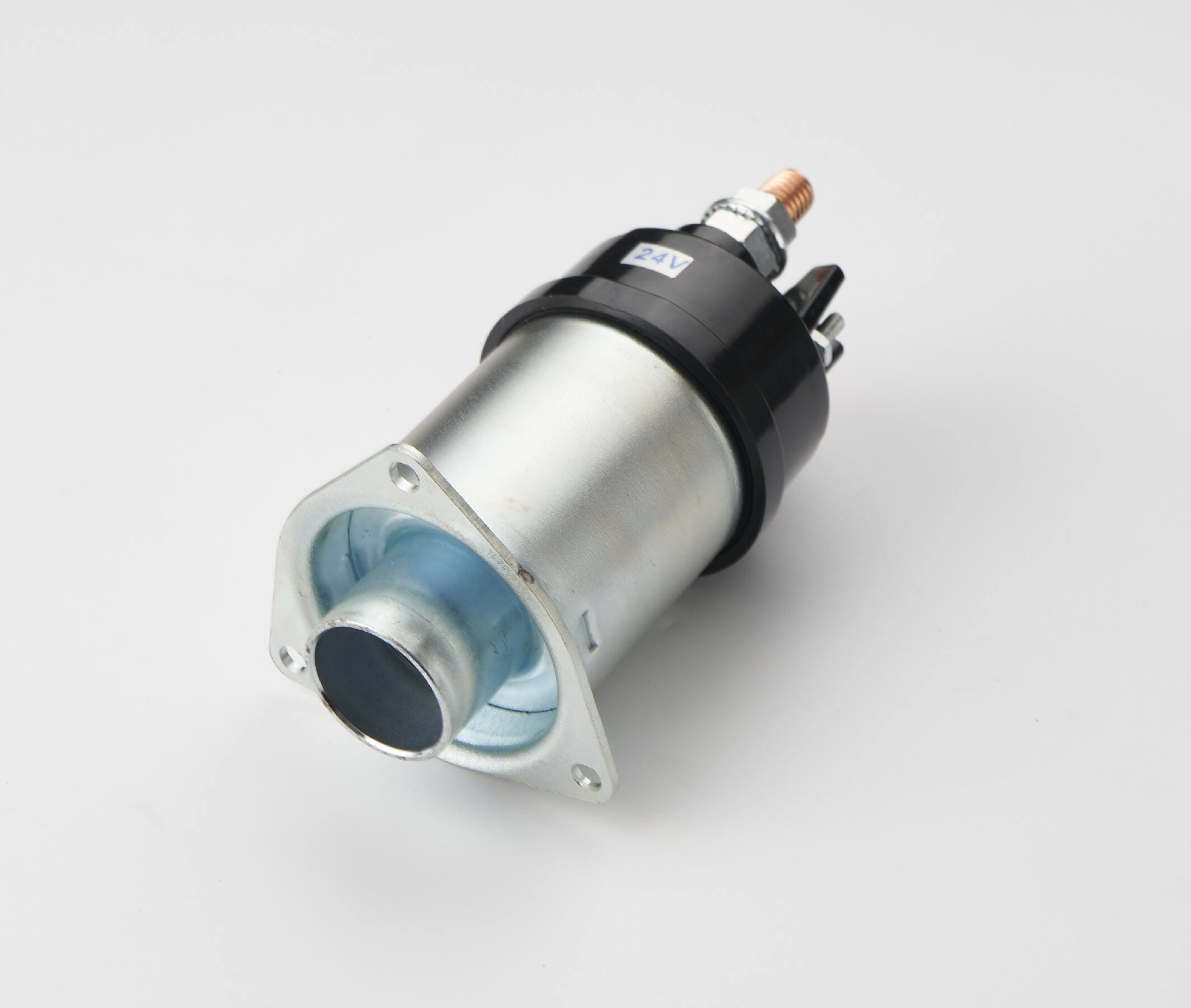
Most automotive starter solenoids feature four main terminals: two large terminals for the high-current path between battery and starter, and two smaller terminals for the control circuit. The control circuit typically receives 12 volts from the ignition system when you turn the key to the start position. Understanding this basic configuration is crucial for effective starter solenoid testing, as it helps you identify which terminals to test and what voltage readings to expect.
Common Failure Modes
Starter solenoid failures typically manifest in several distinct ways that can be identified through systematic testing. Internal contact corrosion represents one of the most common failure modes, where the heavy-duty contacts become pitted or oxidized over time, creating excessive resistance in the high-current path. This condition often produces clicking sounds when attempting to start the engine, as the solenoid energizes but cannot maintain proper contact closure.
Coil winding failures present another frequent problem, where the electromagnetic coil develops open circuits, short circuits, or partial shorts that prevent proper operation. Open coil windings eliminate the solenoid's ability to energize completely, while shorted windings may cause excessive current draw that can damage other starting system components. Mechanical failures, such as stuck plungers or worn contact springs, can also prevent reliable starter solenoid operation and require replacement rather than repair.
Essential Testing Equipment and Safety
Multimeter Selection and Setup
Choosing the appropriate multimeter for starter solenoid testing requires consideration of several key features that ensure accurate measurements and reliable operation. Your multimeter should be capable of measuring DC voltage up to at least 20 volts, resistance from 0.1 ohms to 10,000 ohms, and continuity testing with audible indication. Digital multimeters generally provide better accuracy and easier reading than analog versions, particularly when working in the confined spaces typical of engine compartments.
Before beginning any testing procedures, verify that your multimeter is functioning correctly by testing the battery voltage and checking the continuity function with the test leads touched together. Set the multimeter to the appropriate range for each type of measurement you plan to perform, and ensure the test leads are in good condition with clean, secure connections. Most starter solenoid tests require switching between voltage, resistance, and continuity modes, so familiarize yourself with your specific multimeter's operation beforehand.
Safety Precautions and Preparation
Proper safety procedures are absolutely critical when working with automotive starting systems due to the high currents and voltages involved in starter solenoid operation. Always disconnect the negative battery cable before performing any physical inspections or resistance measurements to prevent accidental short circuits or electrical shock. Wear safety glasses to protect your eyes from potential battery acid splashes or metal debris, and use insulated tools to minimize the risk of creating unintended electrical paths.
Ensure the vehicle is properly secured with wheel chocks and parking brake engagement, particularly if you need to access the starter solenoid from underneath the vehicle. Never attempt to test a starter solenoid while wearing loose jewelry or clothing that could become entangled in moving engine components. Keep a fire extinguisher rated for electrical fires nearby, as starter system malfunctions can occasionally produce sparks or excessive heat that could ignite flammable materials in the engine compartment.
Voltage Testing Procedures
Control Circuit Voltage Verification
Testing the control circuit voltage represents the first critical step in diagnosing starter solenoid problems, as this circuit must provide adequate voltage to energize the electromagnetic coil effectively. Connect your multimeter's positive lead to the small terminal that receives voltage from the ignition switch, and connect the negative lead to a good engine ground or the negative battery terminal. With the multimeter set to DC voltage measurement, have an assistant turn the ignition key to the start position while you observe the voltage reading.
A properly functioning control circuit should deliver between 10.5 and 12.6 volts to the starter solenoid terminal during cranking attempts. Voltage readings below 10.5 volts typically indicate problems with the battery, ignition switch, starter relay, or wiring connections rather than the solenoid itself. Document your voltage measurements for each terminal, as this information will help you distinguish between solenoid failures and external circuit problems that may produce similar symptoms.
High Current Circuit Testing
The high-current circuit test evaluates whether the starter solenoid can effectively close its internal contacts to allow battery voltage to reach the starter motor. Connect the multimeter positive lead to the large terminal that connects to the starter motor, typically marked 'S' or 'Motor,' and connect the negative lead to battery negative. With the ignition key in the start position, you should measure battery voltage at this terminal if the starter solenoid is functioning correctly.
Absence of voltage at the starter motor terminal during cranking indicates that the solenoid contacts are not closing properly, suggesting internal contact failure or coil problems. Voltage readings significantly lower than battery voltage may indicate excessive resistance in the solenoid contacts, which can prevent adequate current flow to the starter motor. Compare your measurements with the vehicle manufacturer's specifications to determine whether the voltage drop across the solenoid falls within acceptable limits.
Resistance and Continuity Testing
Coil Resistance Measurement
Measuring the starter solenoid coil resistance provides valuable insight into the internal condition of the electromagnetic winding that controls solenoid operation. With the battery disconnected for safety, set your multimeter to resistance or ohm measurement mode and connect the test leads across the two small control terminals of the solenoid. Most automotive starter solenoids exhibit coil resistance values between 1.5 and 6 ohms, though specific values vary by manufacturer and application.
An infinite resistance reading indicates an open coil winding that cannot generate the magnetic field necessary for proper operation, while extremely low resistance readings may suggest short circuits within the coil that could cause excessive current draw. Zero resistance typically indicates a direct short that will likely blow fuses or damage other starting system components. Compare your measured resistance values with the manufacturer's specifications, and consider any readings outside the specified range as indications for starter solenoid replacement.
Contact Continuity Verification
Testing the continuity of the high-current contacts reveals whether the solenoid can establish a complete electrical path between the battery and starter motor terminals. With the battery disconnected and the multimeter set to continuity mode, connect the test leads across the two large terminals of the solenoid. Under normal conditions, these contacts should remain open, producing no continuity reading when the solenoid is not energized.
To test contact closure, you can temporarily apply 12 volts across the control terminals using jumper wires connected to the battery, which should cause the solenoid to energize and close the main contacts. When energized, your multimeter should indicate continuity between the large terminals, confirming that the contacts can close properly. If continuity exists without energizing the coil, the contacts may be welded closed, while lack of continuity when energized suggests contact failure or mechanical problems within the starter solenoid assembly.
Advanced Diagnostic Techniques
Voltage Drop Testing Under Load
Voltage drop testing under actual operating conditions provides the most comprehensive evaluation of starter solenoid performance, as it reveals problems that may not be apparent during static testing. This procedure requires measuring the voltage difference across the solenoid while the starter motor is actually drawing current, simulating real-world operating conditions. Connect the multimeter positive lead to the battery-side large terminal and the negative lead to the starter-side large terminal of the solenoid.
During cranking, a healthy starter solenoid should exhibit a voltage drop of less than 0.5 volts across its contacts, indicating minimal resistance in the current path. Voltage drops exceeding 0.5 volts suggest degraded contact surfaces that create excessive resistance and reduce the effective voltage available to the starter motor. This condition can cause slow cranking, intermittent starting problems, or complete starter failure, even when the solenoid appears to function normally during basic continuity testing.
Temperature Effects and Thermal Testing
Temperature variations significantly affect starter solenoid performance, as both electrical resistance and mechanical tolerances change with thermal cycling. Some starter solenoid failures only manifest when the component reaches operating temperature, making cold testing insufficient for complete diagnosis. Allow the engine to reach normal operating temperature before performing thermal testing, or use a heat gun to warm the solenoid assembly while monitoring its electrical characteristics.
Repeat your voltage, resistance, and continuity measurements at elevated temperatures to identify temperature-sensitive failures that could cause intermittent starting problems. Many solenoids that test satisfactorily when cold may exhibit increased resistance, poor contact closure, or coil problems when hot. Document any changes in electrical parameters with temperature, as this information can help predict future reliability issues and determine whether starter solenoid replacement is necessary to prevent unexpected failures.
Interpretation of Test Results
Normal Operating Parameters
Understanding normal starter solenoid operating parameters enables accurate interpretation of your test results and proper diagnosis of starting system problems. Control circuit voltage should remain above 10.5 volts during cranking, with minimal voltage drop between the ignition switch and solenoid control terminal. Coil resistance typically ranges from 1.5 to 6 ohms for most automotive applications, though heavy-duty or commercial vehicle solenoids may exhibit different values.
High-current circuit voltage drop should not exceed 0.5 volts during normal starter operation, ensuring adequate voltage delivery to the starter motor. Contact resistance when closed should measure less than 0.1 ohms in most cases, indicating clean, properly functioning contact surfaces. Any measurements outside these normal ranges suggest starter solenoid degradation or failure that may require attention to maintain reliable vehicle operation.
Failure Pattern Recognition
Different starter solenoid failure modes produce characteristic test result patterns that help identify the specific problem and guide repair decisions. Intermittent starting problems often correlate with marginal voltage drops or temperature-sensitive resistance changes that affect solenoid reliability. Complete starting failure typically results from open coil windings, welded contacts, or severely corroded contact surfaces that prevent proper current flow.
Clicking sounds without starter engagement usually indicate coil energization with failed contact closure, suggesting mechanical problems or severely pitted contact surfaces. Slow cranking may result from excessive voltage drop across degraded solenoid contacts, while complete electrical silence often points to open circuits in the control system rather than solenoid failure. Correlating these symptoms with your test measurements provides a comprehensive picture of starter solenoid condition and helps determine the most appropriate repair approach.
Troubleshooting Common Issues
No-Crank Conditions
When the starter motor fails to engage despite proper ignition switch operation, systematic starter solenoid testing can quickly identify whether the problem lies within the solenoid itself or external components. Begin by verifying control circuit voltage at the solenoid terminal during cranking attempts, ensuring that the ignition system is properly delivering the energizing signal. Absence of control voltage typically indicates problems with the ignition switch, starter relay, neutral safety switch, or associated wiring rather than solenoid failure.
If control voltage is present but the starter motor remains silent, test for voltage at the starter motor terminal of the solenoid during cranking. Lack of voltage at this point with proper control signal indicates internal solenoid contact failure, requiring replacement. However, if voltage appears at both control and motor terminals but the starter still doesn't engage, the problem likely lies within the starter motor itself rather than the starter solenoid assembly.
Intermittent Starting Problems
Intermittent starting issues present unique diagnostic challenges because the starter solenoid may function normally during testing but fail unpredictably during actual use. These problems often result from temperature-sensitive failures, marginal electrical connections, or contact surfaces that function inconsistently due to contamination or wear. Perform multiple test cycles at different temperatures to identify conditions that trigger the intermittent behavior.
Pay particular attention to voltage drop measurements under various operating conditions, as intermittent problems frequently involve marginal contact resistance that varies with temperature, vibration, or current load. Document the specific conditions under which failures occur, such as engine temperature, ambient weather, or time since last successful start. This information helps identify patterns that may not be apparent during single-point testing and guides more targeted diagnostic approaches for elusive starter solenoid problems.
FAQ
How often should I test my starter solenoid
Regular starter solenoid testing is not typically necessary for most vehicles under normal operating conditions, as these components are designed to provide years of reliable service. However, you should test your starter solenoid whenever you experience starting problems such as clicking sounds, intermittent starting, or complete starter failure. Additionally, include solenoid testing as part of comprehensive starting system diagnosis during major service intervals or when replacing other starting system components like the battery or starter motor.
Can a partially failed starter solenoid damage other components
Yes, a partially failed starter solenoid can potentially damage other starting system components through several mechanisms. Excessive voltage drop across degraded solenoid contacts forces the starter motor to draw higher current to achieve the same cranking torque, which can overheat and damage the starter windings. Additionally, intermittent contact closure may create voltage spikes that can affect sensitive electronic components, while welded contacts can cause continuous starter engagement that damages the starter drive mechanism and ring gear.
What tools do I need besides a multimeter for starter solenoid testing
Besides a quality multimeter, you'll need basic hand tools for removing battery connections and accessing the solenoid, including appropriate wrenches or sockets for battery terminals and solenoid mounting bolts. Jumper wires or test leads are essential for applying control voltage during static testing, while a battery load tester can help verify that battery condition isn't affecting your test results. Safety equipment including safety glasses, gloves, and insulated tools are also necessary for safe testing procedures.
How do I distinguish between starter solenoid and starter motor problems
Distinguishing between starter solenoid and starter motor problems requires systematic voltage testing at key points in the starting circuit. If the solenoid receives proper control voltage and delivers battery voltage to the starter motor terminal but the motor still doesn't turn, the problem lies within the starter motor itself. Conversely, if the solenoid fails to deliver voltage to the starter motor despite receiving proper control signals, the solenoid requires replacement. Testing voltage at both the control terminal and motor terminal of the solenoid during cranking attempts provides the definitive information needed to isolate the problem component.