 EN
EN


The starter relay serves as a critical electrical component that controls the flow of power from your vehicle's battery to the starter motor. This small but essential device acts as an electromagnetic switch, enabling high-current electrical connections while protecting the ignition circuit from excessive amperage. Understanding how your starter relay functions and recognizing when it requires testing or replacement can save you from unexpected breakdowns and costly repairs. Modern vehicles rely heavily on these electromagnetic switches to ensure reliable engine starting performance across various operating conditions.
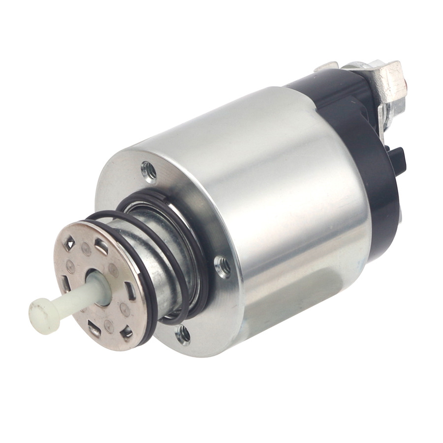
Understanding Starter Relay Functionality
Basic Operating Principles
A starter relay operates on electromagnetic principles, utilizing a low-current control circuit to manage high-current power distribution. When you turn the ignition key or press the start button, a small electrical signal activates the relay coil, creating a magnetic field that closes the high-current contacts. This action allows battery power to flow directly to the starter motor, bypassing the ignition switch and preventing it from handling excessive electrical loads. The relay design protects delicate dashboard components while ensuring adequate power delivery for engine cranking operations.
The electromagnetic coil within the starter relay typically operates on 12 volts in most passenger vehicles, though some commercial applications may utilize 24-volt systems. Internal contacts are designed to handle currents ranging from 30 to 100 amperes, depending on the specific vehicle requirements and starter motor specifications. Quality relays incorporate arc suppression features and robust contact materials to withstand repeated switching cycles without degradation. Understanding these fundamental operating characteristics helps technicians diagnose electrical problems and select appropriate replacement components.
Circuit Integration and Wiring
The starter relay integrates seamlessly with the vehicle's starting circuit, receiving control signals from the ignition switch, neutral safety switch, and clutch pedal switch where applicable. Proper circuit integration ensures that the engine can only be started under safe conditions, preventing accidental engagement while the transmission is in gear. Wire gauge selection and connection quality directly impact relay performance, with undersized conductors potentially causing voltage drops and premature component failure.
Modern vehicles often incorporate the starter relay into a central fuse and relay box, providing easy access for maintenance and troubleshooting procedures. Some advanced systems include additional control modules that monitor starter relay operation and provide diagnostic feedback to the engine management system. Proper understanding of circuit integration helps technicians trace electrical faults and implement effective repair strategies when starter relay problems occur.
Common Starter Relay Failure Symptoms
Electrical Performance Indicators
Failed starter relay components typically manifest through specific electrical symptoms that experienced technicians can readily identify. The most common indication involves a clicking sound from the relay box when attempting to start the engine, suggesting that the electromagnetic coil is activating but the high-current contacts are not closing properly. Intermittent starting problems often indicate worn relay contacts that make inconsistent connections under varying temperature and vibration conditions.
Complete starter relay failure usually results in no audible clicking and no starter motor engagement when the ignition is activated. This symptom can also indicate problems with the ignition switch, neutral safety switch, or wiring harness connections. Experienced diagnosticians understand that systematic testing procedures help isolate the specific component causing starting system malfunctions, preventing unnecessary part replacements and reducing repair costs.
Performance Degradation Patterns
Gradual starter relay degradation often begins with slower engine cranking speeds and may progress to complete starting failure if left unaddressed. Temperature-related symptoms suggest internal component deterioration, with cold weather typically exacerbating existing relay problems. Hot weather can also affect relay performance, particularly in vehicles where the relay box is located near heat sources such as the engine or exhaust system.
Corrosion on relay terminals creates additional resistance in the starting circuit, leading to voltage drops and reduced starter motor performance. Visual inspection of relay terminals and socket connections provides valuable diagnostic information and may reveal obvious problems without requiring electrical testing equipment. Regular maintenance procedures should include cleaning relay terminals and applying appropriate protective coatings to prevent corrosion buildup.
Essential Testing Tools and Equipment
Multimeter Selection and Setup
Professional starter relay testing requires a quality digital multimeter capable of measuring DC voltage, resistance, and continuity accurately. Auto-ranging multimeters provide convenience during diagnostic procedures, automatically selecting appropriate measurement scales and reducing the possibility of operator error. Test lead quality directly impacts measurement accuracy, with heavy-duty leads featuring sharp probe tips and flexible cables proving most suitable for automotive applications.
Multimeter safety ratings should meet or exceed the electrical specifications of the vehicle being tested, with CAT III ratings recommended for automotive diagnostic work. Some advanced multimeters include specialized automotive functions such as pulse width measurement and frequency analysis, which can provide additional diagnostic capabilities when troubleshooting complex starting systems. Proper multimeter calibration and battery maintenance ensure consistent measurement accuracy throughout the testing process.
Additional Diagnostic Equipment
Professional automotive technicians often utilize specialized relay testers that can verify both coil operation and contact performance under simulated load conditions. These devices typically include variable resistance loads and can test relays outside of the vehicle, providing quick go or no-go determinations. Test lights and circuit probes supplement multimeter measurements by providing visual indications of circuit continuity and power availability at specific connection points.
Oscilloscopes enable advanced diagnostics of starter relay switching characteristics and can reveal intermittent problems that might not be apparent during static testing procedures. However, basic multimeter measurements are sufficient for most starter relay diagnostic requirements, making expensive test equipment unnecessary for routine maintenance operations. Proper tool selection depends on the complexity of the electrical system and the level of diagnostic detail required for effective troubleshooting.
Step-by-Step Testing Procedures
Initial Safety Preparations
Before beginning any starter relay testing procedures, technicians must ensure that the vehicle is properly secured and all safety protocols are followed. Parking brake engagement and wheel chocking prevent accidental vehicle movement during testing, while battery disconnect procedures protect both the technician and vehicle electrical systems from potential damage. Proper eye protection and insulated tools reduce the risk of injury from electrical arcs or battery acid exposure.
Engine compartment inspection should precede electrical testing, with particular attention paid to obvious signs of damage, corrosion, or loose connections. Identifying and addressing visible problems before conducting electrical measurements can often resolve starting issues without requiring extensive diagnostic procedures. Documentation of initial vehicle condition and symptoms helps track the effectiveness of repair procedures and provides valuable reference information for future maintenance requirements.
Relay Location and Removal
Locating the starter relay requires consulting the vehicle service manual or fuse box diagram, as relay positions vary significantly between manufacturers and model years. Most vehicles feature labeled relay boxes with removable covers that provide component identification information. Some vehicles utilize multiple relay boxes, requiring careful identification to locate the correct starter relay position.
Relay removal typically involves grasping the component firmly and pulling straight up to disengage the terminal pins from the socket connections. Rocking or twisting motions during removal can damage socket terminals or bend relay pins, potentially causing future connection problems. Proper relay handling prevents damage to delicate internal components and ensures accurate test results throughout the diagnostic process.
Electrical Measurement Techniques
Coil Resistance Testing
Starter relay coil resistance measurements provide fundamental information about electromagnetic component condition and help identify open or short-circuit failures. Typical coil resistance values range from 50 to 200 ohms, depending on the specific relay design and voltage rating. Multimeter resistance measurements should be performed with the relay removed from the circuit to prevent parallel resistance paths from affecting measurement accuracy.
Coil resistance values significantly below specification indicate possible short circuits between coil windings, while infinite resistance readings suggest open circuit conditions. Temperature can affect coil resistance measurements, with cold components typically exhibiting higher resistance values than warm components. Comparing measured values against manufacturer specifications helps determine whether observed variations fall within acceptable tolerance limits.
Contact Continuity Verification
Contact continuity testing involves measuring resistance between the high-current terminals while the relay coil is both energized and de-energized. Proper contact operation should show infinite resistance when the coil is not powered and near-zero resistance when the coil receives appropriate voltage. Contact resistance measurements exceeding one ohm typically indicate worn or corroded contact surfaces that require relay replacement.
Dynamic contact testing involves energizing the relay coil while monitoring contact resistance, allowing technicians to identify intermittent connection problems that might not be apparent during static measurements. Some starter relay designs include normally closed contacts that should exhibit opposite behavior, opening when the coil is energized. Understanding the specific relay configuration prevents misinterpretation of test results and ensures accurate diagnostic conclusions.
Advanced Diagnostic Methods
Load Testing Procedures
Advanced starter relay diagnostics involve testing component performance under actual operating loads, which can reveal problems not apparent during basic resistance measurements. Load testing requires connecting appropriate electrical loads across the relay contacts while monitoring voltage drop and current flow characteristics. Professional relay testers often include variable load capabilities that simulate actual starter motor current requirements.
Voltage drop measurements across energized relay contacts should not exceed 0.5 volts under full load conditions, with lower values indicating better contact condition. Excessive voltage drops suggest increased contact resistance that can reduce starter motor performance and potentially cause starting problems. Load testing provides the most accurate assessment of relay condition and helps predict component reliability under actual operating conditions.
Temperature Cycling Analysis
Temperature cycling tests evaluate starter relay performance across the full range of expected operating conditions, from cold winter starts to hot summer engine compartment temperatures. Some relay failures occur only at specific temperature ranges, making temperature cycling an essential diagnostic procedure for intermittent problems. Professional test equipment can simulate temperature extremes while monitoring electrical performance characteristics.
Thermal shock testing involves rapid temperature changes that can reveal mechanical stress problems within relay components. Solder joint integrity and contact alignment can deteriorate under thermal cycling, leading to intermittent failures that are difficult to diagnose using conventional testing methods. Understanding temperature-related failure modes helps technicians recommend appropriate replacement intervals and preventive maintenance procedures.
Replacement and Installation Guidelines
Component Selection Criteria
Selecting appropriate starter relay replacements requires matching electrical specifications including coil voltage, contact current rating, and terminal configuration. OEM replacement parts typically provide the best compatibility and reliability, though aftermarket alternatives may offer acceptable performance at reduced cost. Coil voltage ratings must match the vehicle electrical system exactly to ensure proper operation and prevent component damage.
Contact current ratings should meet or exceed the original equipment specifications to handle starter motor loads without premature failure. Terminal pin configuration and socket compatibility are critical factors that determine whether a replacement relay will fit properly in the vehicle wiring harness. Some universal starter relay designs offer multiple terminal arrangements but may require wiring modifications for proper installation.
Installation Best Practices
Proper starter relay installation begins with cleaning socket terminals and applying appropriate contact protection to prevent future corrosion problems. Dielectric grease on terminal connections helps exclude moisture while maintaining good electrical conductivity. New relay pins should be inspected for straightness and proper plating before installation to ensure reliable socket engagement.
Installation force should be applied evenly to prevent pin bending or socket damage, with the relay pressed firmly into position until fully seated. Socket retention clips or covers should be properly secured to prevent relay displacement due to engine vibration or thermal cycling. Post-installation testing verifies proper operation and ensures that all circuit connections function correctly under actual operating conditions.
Preventive Maintenance Strategies
Regular Inspection Schedules
Implementing regular starter relay inspection schedules helps identify potential problems before complete failure occurs, reducing the likelihood of unexpected starting system breakdowns. Visual inspections should include checking for corrosion, physical damage, and proper socket engagement every six months or during routine maintenance intervals. Terminal cleaning and protection application can extend relay service life significantly in harsh environmental conditions.
Electrical performance testing during annual maintenance provides baseline measurements that help track component degradation over time. Documenting coil resistance and contact drop measurements creates historical records that enable predictive maintenance strategies. Early identification of performance trends allows scheduled replacement during convenient maintenance windows rather than emergency roadside repairs.
Environmental Protection Measures
Protecting starter relay components from environmental contamination involves ensuring that relay box seals remain intact and that drainage systems function properly. Water intrusion can cause rapid corrosion of relay terminals and socket connections, leading to premature failure even in high-quality components. Regular inspection and replacement of damaged seals prevents moisture-related problems and extends component service life.
Temperature management involves ensuring adequate ventilation around relay boxes and avoiding installation of aftermarket equipment that might increase ambient temperatures. Some performance modifications can generate additional heat that affects nearby electrical components, requiring cooling system upgrades or component relocation. Understanding environmental factors helps technicians recommend appropriate protection measures and maintenance intervals for specific operating conditions.
FAQ
How often should I test my starter relay
Testing your starter relay annually during routine maintenance provides adequate monitoring for most vehicles, though severe operating conditions may require more frequent inspection. Commercial vehicles and those operating in harsh environments should have starter relay testing performed every six months to ensure reliable operation. If you experience intermittent starting problems, immediate testing is recommended regardless of the previous inspection schedule.
Can I drive with a partially failed starter relay
Driving with a partially failed starter relay is not recommended as complete failure can occur without warning, potentially leaving you stranded. Intermittent starting problems typically worsen over time, and the additional stress on other starting system components can cause secondary failures. Replace suspect starter relay components promptly to avoid more extensive and expensive repairs.
What tools do I need for basic starter relay testing
Basic starter relay testing requires a digital multimeter capable of measuring DC voltage, resistance, and continuity. Additional helpful tools include test lights for quick circuit verification and basic hand tools for relay removal and installation. Professional technicians may use specialized relay testers, but multimeter measurements are sufficient for most diagnostic requirements.
Why does my starter relay keep failing repeatedly
Repeated starter relay failures typically indicate underlying problems in the starting circuit, such as excessive current draw from a faulty starter motor, voltage supply issues, or poor connections creating additional resistance. Environmental factors like moisture intrusion or excessive heat can also contribute to premature failure. Comprehensive system diagnosis is necessary to identify and correct the root cause of recurring relay problems.
