When your engine fails to start despite turning the key, the culprit is often a faulty starter solenoid that requires immediate attention. Learning how to repair solenoid starter motor components can save you significant time and money while keeping your equipment operational. This comprehensive guide walks you through the essential steps to diagnose, disassemble, and successfully repair solenoid starter motor systems in approximately 30 minutes using common tools and replacement parts.
Modern starter solenoids serve as electromagnetic switches that engage the starter motor with the engine flywheel during ignition sequences. These critical components endure substantial electrical loads and mechanical stress, making them prone to contact wear, coil degradation, and housing damage over extended use periods. Understanding the fundamental operation principles enables technicians to identify failure patterns and implement effective repair strategies for various solenoid configurations.
Understanding Starter Solenoid Components and Function
Internal Mechanism and Electrical Pathways
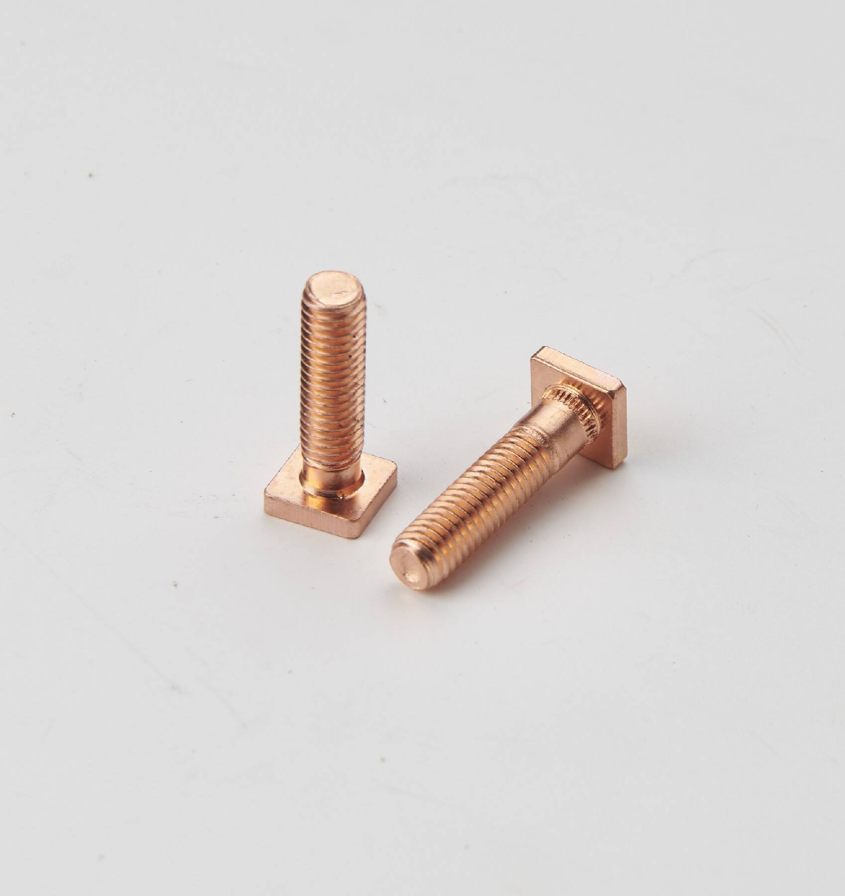
The solenoid assembly consists of an electromagnetic coil, movable plunger, contact disc, and return spring housed within a durable metal casing. When electrical current flows through the coil windings, it generates a magnetic field that pulls the plunger inward, engaging the contact disc to complete the high-current circuit between battery and starter motor. This mechanical action simultaneously pushes the starter drive gear into mesh with the engine flywheel ring gear.
Modern solenoids incorporate dual windings comprising a pull-in coil and hold-in coil that work in sequence to provide strong initial engagement followed by reduced holding current. The pull-in winding creates maximum magnetic force during initial activation, while the hold-in winding maintains plunger position using lower current draw. This design optimizes performance while minimizing heat generation and electrical consumption during extended cranking cycles.
Common Failure Modes and Symptoms
Solenoid failures typically manifest through several distinct symptoms that indicate specific component degradation patterns. Contact disc erosion creates high resistance connections resulting in voltage drops, reduced starter motor performance, and intermittent engagement issues. Coil winding deterioration from heat and vibration leads to reduced magnetic force, slow plunger movement, and eventual complete failure to engage the starter circuit.
Mechanical wear affects plunger movement and contact alignment, causing inconsistent engagement and premature component failure. Environmental factors including moisture intrusion, corrosion buildup, and debris accumulation compound these issues by creating additional resistance and interference with normal operation. Recognizing these symptoms early enables proactive maintenance and prevents costly secondary damage to starter motors and electrical systems.
Essential Tools and Safety Preparations
Required Equipment and Materials
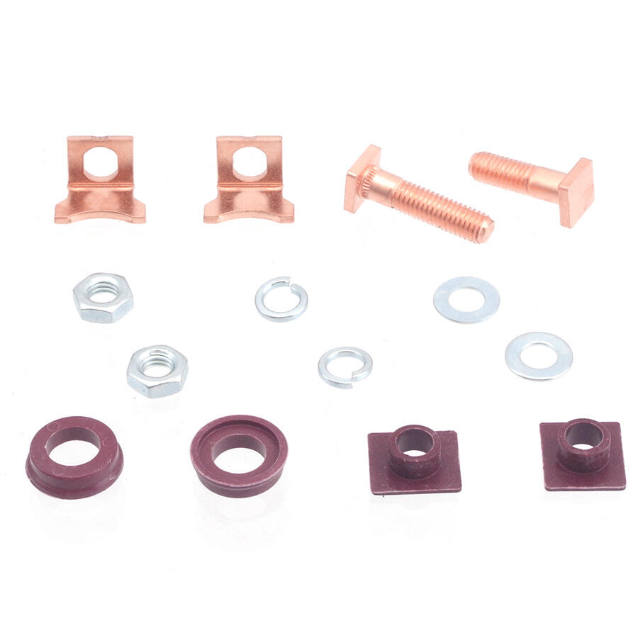
Successful solenoid repair requires basic hand tools including screwdrivers, pliers, wire brushes, and multimeters for electrical testing. Specialized tools such as contact disc pullers and spring compressors facilitate safe disassembly without damaging delicate components. Quality replacement parts including contact discs, springs, and gaskets ensure reliable repairs that withstand operational demands.
Safety equipment including insulated gloves, safety glasses, and work lights provide adequate protection and visibility during repair procedures. Battery disconnect tools and circuit testers prevent accidental electrical contact during diagnosis and repair work. Proper ventilation and fire suppression equipment address potential hazards from electrical arcing and chemical exposure during cleaning operations.
Workspace Setup and Safety Protocols
Establishing a clean, well-lit workspace with adequate ventilation ensures optimal working conditions for precision repair work. Organizing tools and parts systematically prevents loss of small components and maintains efficient workflow throughout the repair process. Disconnecting battery cables eliminates electrical hazards while allowing safe access to starter system components.
Proper lifting and support procedures protect technicians from injury when accessing starter assemblies in confined engine compartments. Using appropriate jack stands, wheel chocks, and lifting equipment ensures stable vehicle positioning during repair operations. Following manufacturer torque specifications and assembly sequences prevents over-tightening and component damage during reassembly procedures.
Step-by-Step Disassembly Process
Initial Inspection and Documentation
Before beginning disassembly, thoroughly inspect the solenoid exterior for obvious damage, corrosion, or loose connections that might indicate underlying problems. Document wire routing and terminal connections using photographs or diagrams to ensure correct reassembly sequence. Testing voltage levels at various points helps identify whether issues originate within the solenoid or external wiring harnesses.
Remove the solenoid from its mounting bracket after disconnecting all electrical connections and support wiring. Clean external surfaces using appropriate solvents to remove dirt, grease, and corrosion that could contaminate internal components during disassembly. Mark component orientation and position to maintain proper alignment during reassembly operations.
Internal Component Removal
Carefully separate the solenoid housing by removing retaining screws or clips that secure the end caps. Extract the plunger assembly slowly while noting spring positioning and contact disc orientation for accurate reassembly. Inspect coil windings for discoloration, burning, or physical damage that indicates electrical overload or thermal stress.
When you need to repair solenoid starter motor systems effectively, examining contact disc wear patterns reveals engagement problems and helps determine replacement requirements. Measure contact disc thickness and inspect surface conditions for pitting, burning, or excessive wear that compromises electrical conductivity. Clean all metal components using wire brushes and appropriate solvents to remove corrosion and contamination.
Component Inspection and Testing Procedures
Electrical Testing Methods
Multimeter testing of coil windings reveals continuity problems and resistance values that indicate coil condition and performance capability. Measure resistance between coil terminals and compare readings to manufacturer specifications to identify partially failed windings. Check for shorts to ground by measuring resistance between coil terminals and the metal housing, which should show infinite resistance in properly functioning units.
Contact disc testing involves checking continuity across the disc surface and measuring resistance values that indicate contact quality. Inspect contact surfaces under magnification to identify micro-cracks, corrosion, or material transfer that affects electrical performance. Test spring tension using calibrated gauges to ensure adequate force for proper contact engagement and release operations.
Mechanical Component Evaluation
Plunger movement inspection focuses on smooth operation without binding, excessive play, or irregular motion patterns. Measure plunger travel distance and compare to specifications to ensure adequate engagement stroke length. Check housing bore dimensions for wear or damage that affects plunger alignment and sealing performance.
Spring condition evaluation includes checking for fatigue cracks, corrosion, or permanent deformation that reduces spring force and affects return operation. Measure spring free length and compression force to verify proper tension characteristics. Inspect mounting brackets and hardware for wear, corrosion, or damage that could affect solenoid positioning and operation.
Repair Techniques and Best Practices
Contact Disc Restoration
Contact disc repair involves careful surface preparation using fine abrasives to remove oxidation and minor pitting while maintaining proper thickness and flatness. Use progressive grits starting with coarse abrasives for heavy material removal followed by fine polishing compounds for smooth surface finish. Avoid excessive material removal that reduces disc thickness below minimum specifications.
When surface damage exceeds repair limits, replacement becomes necessary to ensure reliable electrical connection and long-term performance. Select replacement discs manufactured from appropriate copper alloys that provide optimal conductivity and wear resistance. Proper disc installation requires careful alignment and adequate clearance for smooth plunger operation throughout the engagement cycle.
Coil Winding Maintenance
Coil inspection focuses on identifying damaged insulation, broken conductors, or thermal degradation that compromises electromagnetic performance. Minor insulation damage can often be repaired using appropriate electrical tape or insulating compounds applied according to manufacturer recommendations. However, extensive coil damage typically requires complete replacement to ensure reliable operation.
Cleaning coil assemblies involves removing dirt, moisture, and corrosion using appropriate solvents that do not damage insulation materials. Apply protective coatings to prevent future corrosion and moisture intrusion in harsh operating environments. Ensure proper coil positioning and secure mounting to prevent vibration damage during normal operation cycles.
Reassembly and Testing Procedures
Component Installation Sequence
Begin reassembly by installing cleaned or replacement components in reverse order of disassembly while following documented positioning and orientation marks. Apply appropriate lubricants to moving parts using products recommended for electrical components that do not attract contamination. Ensure proper spring positioning and tension to provide adequate contact force and reliable return operation.
Install new gaskets and seals using appropriate sealants that prevent moisture intrusion while allowing thermal expansion. Torque retaining screws and fasteners to manufacturer specifications using calibrated tools to prevent over-tightening and component damage. Verify proper plunger travel and contact alignment before final assembly completion.
Performance Verification Testing
Conduct comprehensive electrical testing using appropriate test equipment to verify proper coil resistance, contact continuity, and insulation integrity. Apply control voltage while measuring current draw to ensure normal operating parameters and identify potential problems. Test engagement and release cycles multiple times to verify consistent performance and proper timing.
Final installation testing includes checking mounting security, wire routing, and terminal connections for proper torque and corrosion protection. Verify system operation under actual load conditions using appropriate test procedures that simulate normal operating requirements. Document repair work and testing results to maintain accurate service records and warranty compliance.
Troubleshooting Common Installation Issues
Electrical Connection Problems
Poor electrical connections represent the most frequent cause of solenoid performance issues following repair and reassembly operations. Ensure all terminal connections achieve proper torque specifications using calibrated tools to prevent loose connections that create resistance and heat buildup. Apply appropriate anti-corrosion compounds to protect connections from environmental degradation.
Verify correct wire routing and support to prevent vibration damage and interference with other components during normal vehicle operation. Check for proper insulation and protection against sharp edges or heat sources that could damage wiring over time. Test all connections under load conditions to identify intermittent problems that might not appear during static testing.
Mechanical Alignment Issues
Proper solenoid mounting alignment ensures optimal engagement with starter drive mechanisms and prevents premature wear or binding problems. Check mounting bracket condition and hardware tightness to maintain correct positioning throughout operational cycles. Verify adequate clearance around moving components to prevent interference during engagement and release operations.
Adjustment procedures may be required to optimize timing and engagement characteristics for specific applications and operating conditions. Follow manufacturer guidelines for adjustment ranges and locking procedures to maintain calibration under vibration and thermal cycling. Document final adjustment settings for future reference and maintenance operations.
FAQ
How long should a properly repaired solenoid starter motor system last
A professionally repaired solenoid using quality replacement parts typically provides 50,000 to 100,000 operational cycles depending on application severity and maintenance practices. Factors affecting longevity include operating temperature, duty cycle, electrical system condition, and environmental exposure. Regular inspection and preventive maintenance extend service life and identify potential issues before complete failure occurs.
What are the most critical safety considerations when performing solenoid repair work
Always disconnect battery power before beginning any electrical repair work to prevent accidental short circuits and personal injury. Use insulated tools and wear appropriate protective equipment including safety glasses and insulated gloves. Ensure adequate workspace ventilation to prevent accumulation of potentially harmful vapors from cleaning solvents and ensure proper fire suppression equipment is readily available.
Can damaged coil windings be successfully repaired or must they be replaced
Minor coil insulation damage can sometimes be repaired using appropriate electrical tape and insulating compounds, but extensive damage typically requires complete coil replacement. Attempting to repair severely damaged windings often results in reduced performance and premature failure. Professional evaluation helps determine whether repair or replacement provides the most cost-effective solution for specific damage patterns.
What indicates when contact disc replacement is necessary rather than surface restoration
Replace contact discs when material thickness falls below minimum specifications, when pitting or burning extends beyond surface treatment capabilities, or when cracks or deformation affect structural integrity. Surface restoration works well for minor oxidation and light wear, but extensive damage compromises electrical performance and reliability. Measuring disc thickness and evaluating surface condition helps determine the most appropriate repair approach.
Table of Contents
- Understanding Starter Solenoid Components and Function
- Essential Tools and Safety Preparations
- Step-by-Step Disassembly Process
- Component Inspection and Testing Procedures
- Repair Techniques and Best Practices
- Reassembly and Testing Procedures
- Troubleshooting Common Installation Issues
-
FAQ
- How long should a properly repaired solenoid starter motor system last
- What are the most critical safety considerations when performing solenoid repair work
- Can damaged coil windings be successfully repaired or must they be replaced
- What indicates when contact disc replacement is necessary rather than surface restoration