ကားမောင်းသူများ၊ အင်ဂျင်မောင်းသူများနှင့် ကားလျှပ်စစ်စနစ်များပေါ်တွင် အလုပ်လုပ်သည့် အိမ်သုံးအလုပ်သမားများအတွက် အောက်ပါအတိုင်း မှန်ကန်သော ဝိုင်ယာချိတ်ဆက်မှုပုံစံများကို နားလည်ထားရန် အရေးကြီးပါသည်။ စတားတာမော်တာဆိုလီနွိုက် စတာတာမော်တာ ဆောလီနွိုက်သည် စတာတာမော်တာကို ဖလိုင်ဟီလ်နှင့် ချိတ်ဆက်ရန် အရေးပါသော လျှပ်စစ်သံလိုက် ချိတ်ဆက်မှုဖြစ်ပြီး စနစ်တကျ အလုပ်လုပ်နေရန်အတွက် မှန်ကန်သော ဝိုင်ယာချိတ်ဆက်မှုများကို အထူးအရေးပေးရပါသည်။ အရောင်သတ်မှတ်ချက်များသည် ကားအများအပြားတွင် တူညီသော ထားရှိမှုများကို အာမခံပေးပြီး မှားယွင်းသော ဝိုင်ယာချိတ်ဆက်မှုများနှင့် စနစ်ပျက်စီးမှုများ သို့မဟုတ် ဘေးအန္တရာယ်များကို လျှော့ချပေးပါသည်။
စတားတာမော်တာဆိုလီနွိုက်ပစ္စည်းများကို နားလည်ခြင်း
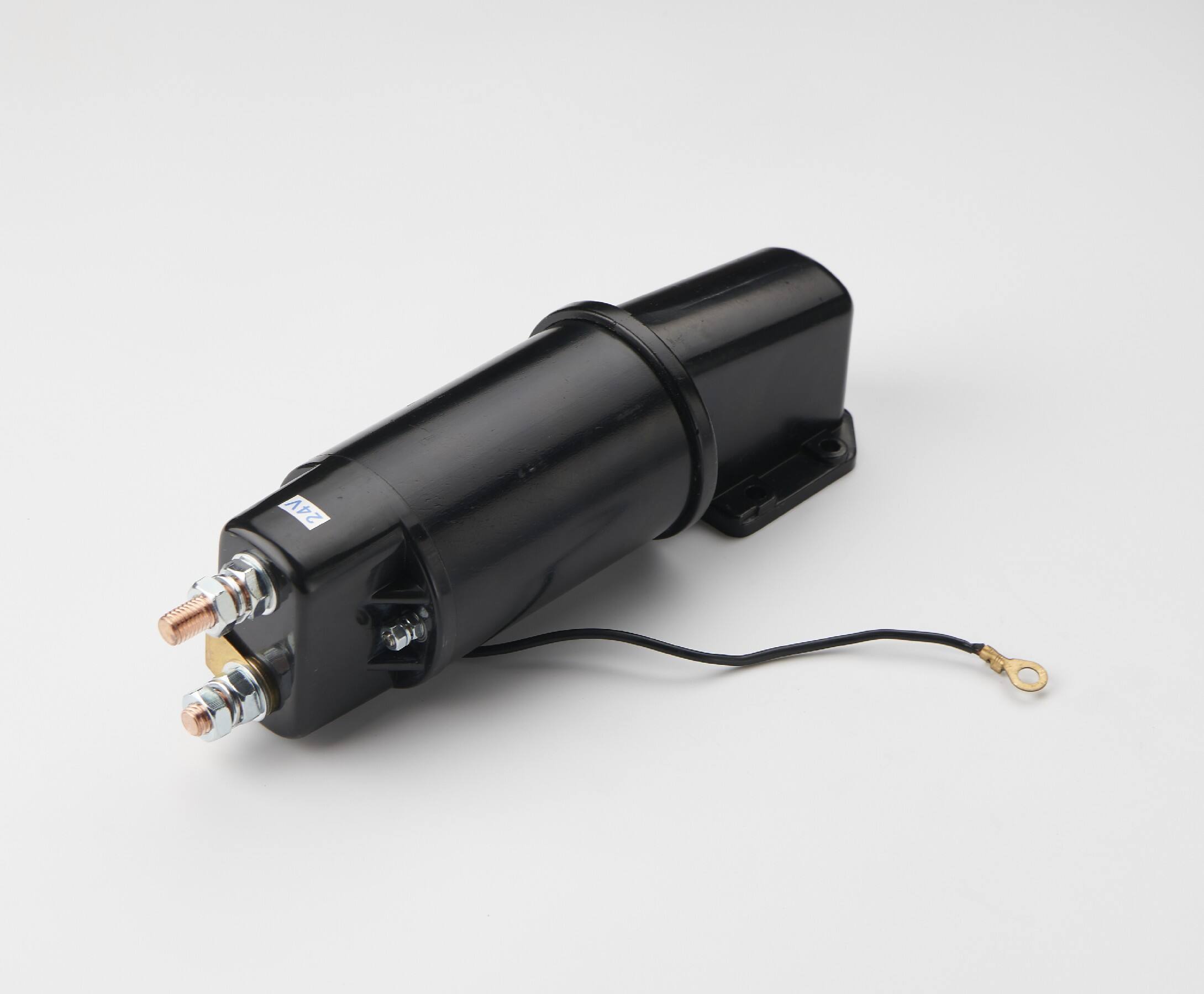
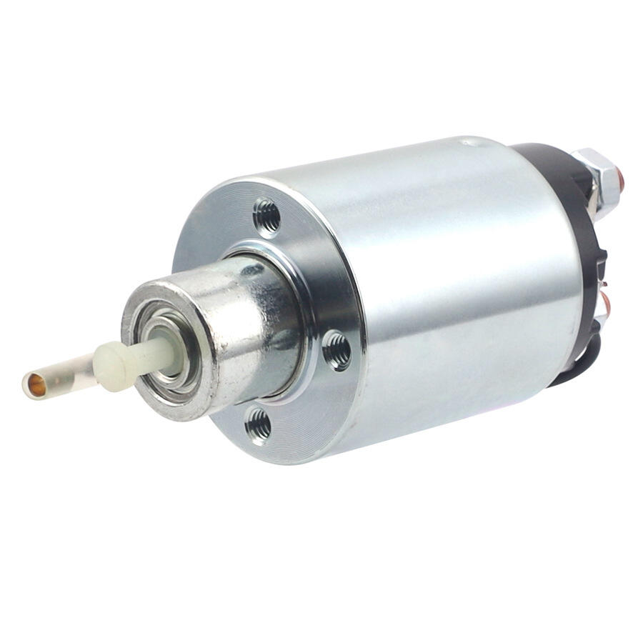
အတွင်းပိုင်းဖွဲ့စည်းပုံနှင့် လုပ်ဆောင်ချက်
စတာတာမော်တာဆောလီနွုိက်သည် အင်ဂျင်စတာတ်လုပ်ဆောင်မှုများကို အောင်မြင်စေရန် အတူတက်လုပ်ဆောင်သည့် အရေးကြီးသော အစိတ်အပိုင်းများစွာပါဝင်ပါသည်။ လျှပ်စစ်သံလိုက်ကွေးကြောင်းသည် လျှပ်စစ်စီးကြောင်းဖောက်ပေးသည့်အခါ သံလိုက်ကွေးအား ထုတ်လုပ်ပီး ပလန်ဂျာစနစ်ကို ဘက်ထရီနှင့် စတာတာမော်တာအကြား ဆက်သွယ်မှုကို ပြည့်စုံစေရန် နေရာသို့ ဆွဲခေါ်ပေးပါသည်။ ဤလုပ်ဆောင်မှုသည် စတာတာမော်တာ မော်တာသို့ ချိတ်ဆက်မှုကို ဖောက်ပေးခြင်းနှင့် ဖလိုင်ဟီလ် ရင်းဂီယာနှင့် တစ်ပါတည်း ချိတ်ဆက်မှုကို ဖောက်ပေးခြင်းကို တစ်ပါတည်း လုပ်ဆောင်ပါသည်။ ထို့ကြောင့် အင်ဂျင်ကို လည်ပတ်စေရန် လိုအပ်သည့် ယန္တရားဆိုင်ရာ ချိတ်ဆက်မှုကို ဖန်တီးပေးပါသည်။ ဆောလီနွုိက် အိမ်အုပ်သည် အများအားဖြင့် လျှပ်စစ်ဆက်သွယ်မှုများအတွက် သီးခြားသီးခြား ရည်ရွယ်ချက်များရှိသည့် အဆက်များစွာပါဝင်ပါသည်။
စတာတာမော်တာဆိုလီနွိုက်ဒ်အတွင်းရှိ အတွင်းပိုင်းထိတ်တွေ့မှုများကို သေးငယ်သော လျှပ်စီးကြောင်းအားများကို ကိုင်တွယ်နိုင်ရန် ဒီဇိုင်းထုတ်ထားပြီး အက်တီဗေးရှင်း ထောင်နှစ်ချီ၍ အကောင်အထည်ဖော်မှုများအတွင်း ယုံကြည်စိတ်ချရသော လျှပ်စီးကြောင်းပေးပို့မှုကို ထိန်းသိမ်းပေးပါသည်။ စပရင်ဖြင့် ပြန်လည်တပ်ဆင်ထားသော ပြန်လည်ထုတ်လုပ်မှုစနစ်သည် အီဂျင်နီရှင်နှိပ်ကွပ်မှုကို ဖြုတ်လေးပေးပြီးနောက် စတာတာမော်တာကို မှန်ကန်စွာ ဖြုတ်လေးပေးရန် သေချာစေပါသည်။ ထိုသို့ဖြုတ်လေးမှုများမှုန်းခြင်းဖြင့် စတာတာမော်တာနှင့် ဖလိုင်ဝီလ်နှစ်များကို ပျက်စီးမှုများမှ ကာကွယ်ပေးပါသည်။ ဤအတွင်းပိုင်းအစိတ်အပိုင်းများကို နားလည်ခြင်းဖြင့် နည်းပညာပုဂ္ဂိုလ်များသည် ပြဿနာများကို ပိုမိုထိရောက်စွာ ရှာဖွေဖော်ထုတ်နိုင်ပါသည်။ ထို့အတူ စတာတာစနစ်များကို ပြုပြင်ထိန်းသိမ်းရာတွင် သင့်တော်သော အစိတ်အပိုင်းများကို ရွေးချယ်နိုင်ပါသည်။
ထိတ်တွေ့မှုအများအပြားကို သတ်မှတ်ခြင်း စံနှုန်းများ
စတာတာမော်တာ ဆောလီနွုိက်ဒ် ယူနစ်များအများစုတွင် စတာတ်အေးမ်စီစီတီအတွင်းရှိ သတ်မှတ်ထားသော ဆာကျူးလုပ်ဆောင်ချက်များနှင့် ကိုက်ညီသည့် စံသတ်မှတ်ထားသော ထာမီနယ်အမှတ်အသားများ ပါဝင်ပါသည်။ ဘက်ထရီထာမီနယ်သည် ပုံမှန်အားဖြင့် ဘက်ထရီ၏ အပေါ်ပိုင်းကြိုးနှင့် တိုက်ရိုက်ချိတ်ဆက်ပါသည်။ ထိုသို့ဖြင့် စတာတ်အေးမ်လုပ်ဆောင်ရှိ လျှပ်စီးအပြည့်အဝကို မော်တာဝိုင်န်ဒင်းများသို့ ပို့ဆောင်ပေးပါသည်။ အီဂျင်နီရှင်ထာမီနယ်သည် သော့ကို စတာတ်အေးမ်အနေဖြင့် လှည့်လိုက်သည့်အခါ အီဂျင်နီရှင်စွစ်ခ်မှ လျှပ်စီးကို လက်ခံရရှိပါသည်။ ထိုသို့ဖြင့် လျှပ်စီးသံသော ကွေးလ်ကို လှုံ့ဆော်ပေးပါသည်။ အချို့သော ဆောလီနွုိက်ဒ်များတွင် အပ်စ်က်စ်စ်များ သို့မဟုတ် ဘိုင်ပါစ်ဆာကျူးများအတွက် အပ доп ထာမီနယ်များ ပါဝင်ပါသည်။ ထိုသို့သော ထာမီနယ်များသည် ကရန်ကင်းလုပ်ဆောင်မှုအတွင်း အချို့သော စနစ်များသို့ လျှပ်စီးကို ဆက်လက်ပေးနေပါသည်။
ထိပ်တွင် တပ်ဆင်ရန် အရွယ်အစားနှင့် ချောင်းမှုန်းသည်လည်း စံသတ်မှတ်ချက်များနှင့် ကိုက်ညီပါသည်။ ထိုသို့ဖြင့် ချောင်းမှုန်းချိတ်ဆက်မှု၏ စုံလင်မှုကို အာမခံပြီး ဗိုလ်တော်မှုန်း (vibration) သို့မဟုတ် အပူချိန်ပြောင်းလဲမှု (thermal cycling) ကြောင့် ချောင်းမှုန်း ဖွင့်လေးခြင်းကို ကာကွယ်ပေးပါသည်။ ချောင်းမှုန်းများကို တင်းကြပ်ရာတွင် သတ်မှတ်ထားသော တင်းကြပ်မှုအား (torque specifications) ကို စနစ်ကျစွာ လိုက်နာရပါမည်။ ထိုသို့ဖြင့် ဆိုလီနွိုက်ဒ်အိမ်အုပ် (solenoid housing) ကို ပျက်စီးမှုမှ ကာကွယ်ပေးပြီး လျှပ်စစ်ဆက်သွယ်မှုအတွက် လုံလောက်သော ထိတ်တွေ့မှုကို အာမခံပေးပါသည်။ ဤစံသတ်မှတ်ထားသော ပုံစံများသည် ကွဲပားသော ယာဉ်ပလက်ဖောင်းများနှင့် ထုတ်လုပ်သူများတွင် အခက်အခဲရှာဖွေရေးလုပ်ထုံးများနှင့် အစိတ်အပိုင်းများ အစားထိုးရေးလုပ်ထုံးများကို ရှင်းလင်းစေပါသည်။
ယေဘုယျ အရောင်ကုဒ်စံသတ်မှတ်ချက်များ
အဓိက စီးကရ်ကွစ် သတ်မှတ်ခြင်း
ကားများတွင် အသုံးပြုသည့် ဝိုင်ယာများ၏ အရောင်များကို စံနှုန်းထားသည့် လုပ်ငန်းစဥ်များအရ သတ်မှတ်ထားပါသည်။ ဤစံနှုန်းများသည် နည်းပညာပုဂ္ဂိုလ်များအား ဆားကူးစက်လုပ်ငန်းများကို မြန်မြန်စိမ်းနောက်ခံဖော်ပြန်လုပ်နိုင်ရန်နှင့် ကားတစ်စီးလုံးတွင် လျှပ်စစ်လမ်းကြောင်းများကို ခြေရာခံနိုင်ရန် အထောက်အကူပေးပါသည်။ စတာတာမော်တာ ဆောလီနွိုက်ဒ် ဆားကူးစက်လုပ်ငန်းတွင် အများအားဖြင့် အသေးစိတ်သတ်မှတ်ထားသည့် အရောင်များကို အသုံးပြုပါသည်။ ဤအရောင်များသည် အသေးစိတ်သတ်မှတ်ထားသည့် စီးဂနယ်များနှင့် ပါဝါချိတ်ဆက်မှုများအတွက် အသုံးပြုပါသည်။ အထူးသဖြင့် အနီရောင် သို့မဟုတ် အဝါရောင် ဝိုင်ယာများကို ဘက်ထရီဗို့အားကို အဓိက ပါဝါချိတ်ဆက်မှုသို့ ပို့ဆောင်ရန် အသုံးပြုလေ့ရှိပါသည်။ အမဲရောင် ဝိုင်ယာများသည် အများအားဖြင့် ဂရောင်းဒ်ချိတ်ဆက်မှုများကို ဖော်ပြပါသည်။ အသေးစိတ်သတ်မှတ်ထားသည့် ဝိုင်ယာများ (အရောင်အမျိုးမျိုးဖြင့်) သည် အီဂ်နီရှင်စ်ဝိုင်ခ် နှင့် အခြားသော စနစ်များမှ ထုတ်လုပ်သည့် ထိန်းချုပ်မှုစီးဂနယ်များကို ပို့ဆောင်ရန် အသုံးပြုပါသည်။
ဤအရောင်သတ်မှတ်ခြင်းစည်းမျဉ်းများကို ဆောလီနွိုက်ချိတ်ဆက်မှုများသာမက စတင်ခြင်းစက်ဝိုင်းတစ်ခုလုံး (အထူးသဖြင့် အီဂျင်နီရှင်စ်ဝိုင်း၊ နျူထရယ်လုံခြုံရေးစွပ်စွပ်နှင့် သက်ဆိုင်ရာ ရီလေးစက်ဝိုင်းများ) တွင်ပါ အသုံးပြုကြသည်။ အရောင်သတ်မှတ်ခြင်းတွင် သေချာမှန်ကန်မှုရှိခြင်းဖြင့် နည်းပညာပုဂ္ဂိုလ်များသည် မသိရှိသော ယာဉ်များပေါ်တွင် ထိရောက်စွာ အလုပ်လုပ်နိုင်ပြီး လျှပ်စစ်ပစ္စည်းများကို ပျက်စီးစေနိုင်သည့် မှားယွင်းသော ချိတ်ဆက်မှုများ သို့မဟုတ် ဘေးအန္တရာယ်ဖြစ်စေနိုင်သည့် ချိတ်ဆက်မှုများကို လျှော့ချပေးနိုင်သည်။ ခေတ်မှီယာဉ်များတွင် ကွန်ပျူတာထိန်းချုပ်သော စတင်စနစ်များနှင့် ခိုးယူမှုကာကွယ်ရေးလုပ်ဆောင်ချက်များအတွက် အရောင်အသစ်များကို ထည့်သွင်းအသုံးပြုလေ့ရှိသည်။
ဒုတိယအဆင့် စက်ဝိုင်းအသုံးပြုမှုများ
စတာတာမော်တာဆိုလီနွိုက်ဒ်နှင့် ချိတ်ဆက်ထားသော ဒုတိယအားပေးစက်ဝိုင်းများသည် အထူးလုပ်ဆောင်ချက်များဖြစ်သည့် အီဂျင်နေရှင်စနစ်ကို ကျော်လွန်ခြင်း၊ အပိုပစ္စည်းများအတွက် ပါဝါကို ထိန်းသိမ်းခြင်း သို့မဟုတ် စနစ်စောင်းကြည့်ခြင်းအတွက် ပြန်လည်အက်ဆ်စ်ပေးခြင်းတို့ကို မက်ထားပါသည်။ ဤစက်ဝိုင်းများသည် အဓိကပါဝါနှင့် ထိန်းချုပ်မှုချိတ်ဆက်မှုများမှ ကွဲပြားစေရန် အထူးရောင်စင်များဖြင့် ပြုလုပ်ထားသည့် ဝိုင်ယာများကို အသုံးပြုလေ့ရှိပါသည်။ ချိတ်ဆက်မှုများကို ကျော်လွန်ခြင်းအတွက် အသုံးပြုသည့် ပါပူရယ် (Purple) သို့မဟုတ် ဘရောင် (Brown) ရောင်ဝိုင်ယာများသည် စတာတာမော်တာကို လည်ပုတ်နေစဉ်အတွင် အီဂျင်နေရှင်စနစ်အား ပါဝါပေးနေခြင်းကို ထိန်းသိမ်းပေးသည့် စက်ဝိုင်းများကို ဖော်ပြပါသည်။ အနီရောင် (Green) သို့မဟုတ် အပ်ပ်လူ (Blue) ရောင်ဝိုင်ယာများသည် အီဂျင်စီမှန်းမှုစနစ်များ သို့မဟုတ် လုံခြုံရေးမော်ဂျူလ်များသို့ ပြန်လည်အက်ဆ်စ်ပေးသည့် စက်ဝိုင်းများကို ဖော်ပြပါသည်။
အပိုပစ္စည်းများကို တပ်ဆင်ခြင်း သို့မဟုတ် စတာတာမော်တာအား အခါအားလိုက် မလုပ်ဆောင်နိုင်ခြင်းကို စစ်ဆေးရှာဖွေခြင်းအတွက် ဒုတိယအားပေးစက်ဝိုင်းများ၏ ရောင်စင်ကုဒ်များကို နားလည်ထားခြင်းသည် အထူးအရေးကြီးပါသည်။ အချို့သော ယာဉ်များတွင် စနစ်တွင် အသုံးပြုသည့် ဆိုလီနွိုက်ဒ်များ သို့မဟုတ် ရီလေးများကို တစ်ခါတည်း အသုံးပြုထားပါသည်။ ထိုသို့သော စနစ်များကို တပ်ဆင်ရာတွင် ဝိုင်ယာများ၏ လမ်းကြောင်းနှင့် ချိတ်ဆက်မှုအစဥ်များကို သေချာစွာ စောင်းကြည့်ရန် လိုအပ်ပါသည်။ ဤရောင်စင်ကုဒ်များကို စနစ်တက်မှုအတွက် မှန်ကန်စွာ မှတ်တမ်းတင်ထားခြင်းဖြင့် ပြင်ဆင်မှုများ သို့မဟုတ် ပြောင်းလဲမှုများကို အောင်မွေးစေရန် အထောက်အကူဖော်ပေးပါသည်။ ထို့အပါအဝါ စနစ်၏ ယုံကြည်စိတ်ချရမှုနှင့် လုံခြုံရေးစံနှုန်းများကို ထိန်းသိမ်းပေးပါသည်။
တပ်ဆင်မှုနှင့် ဝိုင်ယာချိတ်ဆက်မှုလုပ်ထုံးများ
တပ်ဆင်မတိုင်မီ လုံခြုံရေးဆိုင်ရာ အစီအမံများ
စက်နှိုးစက်၏ solenoid ကြိုးတန်းများအား စတင်မွမ်းမံမွမ်းမံမပြုလုပ်မီတွင် စက်မှုပညာရှင်များသည် မတော်တဆ လျှပ်စစ်ဓာတ်အားခွေအတို သို့မဟုတ် လျှပ်စစ်ဓာတ်အားပြန့်ပွားမှု အန္တရာယ်ကို ကာကွယ်ရန်အတွက် ယာဉ်ဘက်ထရီကို ချိတ်ဆက်ထားခြင်းမှ ပယ်ဖျက်ရမည်။ စတာတာပတ်များ၏ စွမ်းအားမြင့်မားမှုကြောင့် လုံခြုံရေးဆိုင်ရာ သတိပြုချက်များကို ချမှတ်ရန် လိုအပ်ပြီး မမှန်မကန် ကိုင်တွယ်ခြင်းသည် ပြင်းထန်သော ဒဏ်ရာ သို့မဟုတ် အစိတ်အပိုင်း ပျက်စီးမှုများကို ဖြစ်ပေါ်စေနိုင်သည်။ ကိရိယာများနှင့် အလုပ်မျက်နှာပြင်များ အားလုံးကို သန့်ရှင်းခြောက်သွေ့စေပြီး တပ်ဆင်စဉ် တစ်လျှောက်လုံး တစ်ကိုယ်ရေ ကာကွယ်ရေး ပစ္စည်းများ တပ်ဆင်ထားရန် လိုအပ်သည်။
ပြုပြင်ထိန်းသိမ်းမှုပြုလုပ်ရန် လိုအပ်သော အထူးနည်းလမ်းများ သို့မဟုတ် သတိပြုစရာများ ရှာဖွေရန်အတွက် ယာဉ်အလိုက် ပြုပြင်ထိန်းသိမ်းမှု အချက်အလက်များကို သုံးသပ်သင့်သည်။ တချို့ကားတွေမှာ အစပျိုးစက်ရဲ့ solenoid အစားထိုးခြင်း (သို့) ဝိုင်ယာကြိုး ပြုပြင်ခြင်းမှာ သီးခြား အစီအစဉ်တွေ လိုအပ်တဲ့ လုံခြုံရေးစနစ် (သို့) ကွန်ပြူတာ မော်ဂျူးတွေ တပ်ဆင်ထားပါတယ်။ ပတ်လမ်းချိတ်ဆက်မှုအားလုံးကို မှန်ကန်စွာ ဖော်ထုတ်ခြင်းသည် တပ်ဆင်မှုဖြစ်စဉ်အတွင်း စျေးကြီးသော အီလက်ထရောနစ် အစိတ်အပိုင်းများကို မရည်ရွယ်ဘဲ ပျက်စီးစေခြင်းမှ ကာကွယ်ပေးပါသည်။
ချိတ်ဆက်မှုအစီအစဥ်နှင့် တော်ကျူးသတ်မှတ်ချက်များ
ထည့်သွင်းတပ်ဆင်မှုအတွင်း စတားတာမော်တာဆိုလီနွိုက် ချိတ်ဆက်မှုအစီအစဥ်သည် စနစ်၏ မှန်ကန်စွာလည်ပတ်မှုနှင့် ဘေးကင်းလုံခြုံမှုကို အာမခံရန် ယုက္တိကျသော အဆင့်ဆင့်ဖြစ်ပါသည်။ မှုခ်ခ်မှုမှုအတွင်း မတော်မကျော်စွာ ဖွင့်လှစ်မှုမှုကို ကာကွယ်ရန်အတွက် ဘက်ထရီချိတ်ဆက်မှုများကို အများအားဖြင့် နောက်ဆုံးတွင် ပြုလုပ်သင့်ပါသည်။ ထို့အတူ စီးရီးလမ်းကြောင်းများကို မှန်ကန်စွာ စီစဥ်ရန်အတွက် ထိန်းချုပ်ချိတ်ဆက်ကြိုးများကို အရင်ဆုံး ချိတ်ဆက်နိုင်ပါသည်။ အဆိုပါ ချိတ်ဆက်မှုတိုင်းတွင် လျှပ်စစ်ဆက်သွယ်မှုကို ယုံကြည်စွာ ထောက်ပံ့ပေးနိုင်ရန်အတွက် သင့်လျော်သော တော်ကျူးသတ်မှတ်ချက်များကို လိုက်နာရပါမည်။ သို့သော် အလွန်ကြီးမားသော တော်ကျူးဖြင့် ချိတ်ဆက်မှုကို လုပ်ခြင်းသည် ချိတ်ဆက်မှုနေရာများ (threads) သို့မဟုတ် အိမ်အုပ်များ (housing materials) ကို ပျက်စီးစေနိုင်ပါသည်။
ဝိုင်ယာများကို စီစဉ်ရာတွင် အပူအိုးများ၊ ရှုပ်ထွေးနေသော အစိတ်အပိုင်းများနှင့် ဝိုင်ယာများကို အလွန်မှုန်းခြင်းဖြစ်စေနိုင်သည့် နေရာများကို ထည့်သွင်းစဉ်းစားရမည်။ ဝိုင်ယာဟာန်နက်များကို သင့်လျော်စွာ ချောင်နေစေခြင်းဖြင့် အင်ဂျင်အလုပ်လုပ်မှုကို အနှောင့်အယှက်မဖြစ်စေဘဲ နောင်တွင် ပြုပြင်မှုလုပ်ရာတွင် လွယ်ကူစွာ ဝင်ရောက်နိုင်ရန် ထောက်ပံ့ပေးပါသည်။ သင့်လျော်သော ကွန်နက်တာများနှင့် ထိပ်ဖျားများကုန် အရည်အသွေးမြင့် လျှပ်စစ်ဆက်သွယ်မှုများကို အသုံးပြုခြင်းဖြင့် စက်မှုအခြေအနေများနှင့် သဘောတော်ပါသည့် ပတ်ဝန်းကျင်အခြေအနေများအောက်တွင် စတာတ်စနစ်၏ ရှည်လျားသော ယုံကြည်စိတ်ချရမှုကို အာမခံပေးပါသည်။
အဖြစ်များသော ဝိုင်ယာပြဿနာများကို ရှာဖွေဖြေရှင်းခြင်း
ရောဂါရှာဖွေခြင်း လုပ်ငန်းစဉ်များနှင့် စမ်းသပ်မှုနည်းလမ်းများ
စတာတာမော်တာ ဆောလီနွိုက်ဒ် ဝိုင်ယ်ရင်းပြဿနာများကို စနစ်တကျ ရှာဖွေဖေးဖေးခြင်းသည် ချိတ်ဆက်မှုအားလုံးနှင့် ဝိုင်ယ်ကြိုးအခြေအနေများကို မြင်သာသော စစ်ဆေးမှုဖြင့် စတင်ပါသည်။ လွဲချော်နေခြင်း၊ ချေးတက်နေခြင်း သို့မဟုတ် ပျက်စီးနေခြင်းတို့ကြောင့် စတင်မှုပုံမှန်မဟုတ်သော ပြဿနာများ ဖြစ်ပေါ်လေ့ရှိပြီး မှန်ကန်သော စစ်ဆေးမှုနည်းလမ်းများမရှိပါက ရှာဖွေဖေးဖေးရန် ခက်ခဲပါသည်။ ချိတ်ဆက်မှုများတွင် ဗို့အားကျဆင်းမှု စစ်ဆေးခြင်းဖြင့် မြင်သာသော စစ်ဆေးမှုတွင် မသိသာသော အချိန်မှုန်းများကို ရှာဖွေဖေးဖေးနိုင်ပါသည်။ ဆက်သွယ်မှု စစ်ဆေးခြင်းဖြင့် စတင်မှုစနစ်တွင် စက်ဝိုင်းအားလုံး အပြည့်အဝ အလုပ်လုပ်နေကြောင်း အတည်ပြုနိုင်ပါသည်။
ပရော်ဖက်ရှင်နယ် ရှာဖွေဖေးဖေးပိုင်းဆော့ဖ်ဝဲများသည် စတာတာမော်တာ ဆောလီနွိုက်ဒ်၏ လုပ်ဆောင်ချက်အကြောင်း အမှန်တကယ် ကရန်ကင်းလုပ်ဆောင်နေစဉ် အချိန်များတွင် အရေးကြီးသော အချက်အလက်များကို ပေးစေပါသည်။ လျှပ်စီးကြောင်း စုပ်ယူမှု တိုင်းတာမှုများသည် စတာတာမော်တာအတွင်းရှိ စက်မှုပြဿနာများကို ရှာဖွေဖေးဖေးရန် အထောက်အကူပေးပါသည်။ ထိုပြဿနာများသည် ဆောလီနွိုက်ဒ် ထိပ်ဖျားများပေါ်တွင် အလွန်အမင်း ဖိအားများကို ဖေးဖေးပေးနေနိုင်ပါသည်။ လုပ်ဆောင်နေစဉ် အပူချိန် တိုင်းတာမှုများသည် အပူလွန်ကြောင်း အခြေအနေများကို ဖေးဖေးပေးပါသည်။ ထိုအခြေအနေများသည် မှန်ကန်သော ဝိုင်ယ်ရင်းများ မရှိခြင်း၊ မလုံလောက်သော ချိတ်ဆက်မှုများ သို့မဟုတ် အစိတ်အပိုင်းများ ပျက်စီးနေခြင်းတို့ကြောင့် ဖြစ်ပေါ်လေ့ရှိပါသည်။
အဖြစ်များသော ပျက်စီးမှုပုံစံများနှင့် ဖြေရှင်းနည်းများ
အပူနှင့်ဆိုင်သော ပျက်စီးမှုများသည် စတာတာမော်တာ ဆိုလီနွိုက် ဝိုင်ယ်ရင်းစနစ်များကို ထိခိုက်စေသည့် အဖြစ်များသော ပျက်စီးမှုအမျိုးအစားများထဲမှ တစ်ခုဖြစ်သည်။ ချိတ်ဆက်မှုများတွင် အလွန်အများကြီးသော ပုံမှန်မဟုတ်သော ခုခံမှုများကြောင့် ဒေသတွင်းအပူချိန်များ မြင့်တက်လာပြီး ဝိုင်ယ်ကြေးများ၏ အထုပ်များ အရည်ကျစေခြင်း၊ ထိပ်ဖျားများ ပျက်စီးစေခြင်း သို့မဟုတ် အခါအားလျော်စွာ ချိတ်ဆက်မှုများ ဖြစ်ပေါ်စေခြင်းတို့ကို ဖြစ်ပေါ်စေနိုင်သည်။ ဘက်ထရီ ထိပ်ဖျားများ၊ ဆိုလီနွိုက် ချိတ်ဆက်မှုများနှင့် ဂရှုန်း စက်ဝိုင်းများကို ပုံမှန်စစ်ဆေးခြင်းနှင့် ထိန်းသိမ်းခြင်းများသည် ယင်းကဲ့သို့သော အပူနှင့်ဆိုင်သော ပျက်စီးမှုများကို ကာကွယ်ရန် အထောက်အကူပေးပါသည်။ ထိုပျက်စီးမှုများကြောင့် ယာဉ်များသည် အသိပေးခြင်းမရှိဘဲ အလုပ်မလုပ်တော့ပါ။
ကြွေလှုပ်မှုနှင့် ယန္တရားဆိုင်ရာ ဖိအားများသည်လည်း စတာတာမော်တာ ဆိုလီနွိုက် ဝိုင်ယ်ရင်းပြဿနာများကို ဖော်ပေါ်စေသည့် အကြောင်းရင်းများဖြစ်ပါသည်။ အထူးသဖြင့် အလေးချိန်များသော အသုံးပျော်များ သို့မဟုတ် ပြင်ပပတ်ဝန်းကျင် အခက်အခဲများရှိသော နေရာများတွင် အလုပ်လုပ်သည့် ယာဉ်များတွင် ထိုကဲ့သို့သော ပြဿနာများ ပိုမိုဖော်ပေါ်လေ့ရှိပါသည်။ ဝိုင်ယ်ကြေးများကို သင့်လျော်စွာ ချိတ်ဆက်ခြင်းနှင့် လမ်းကြောင်းသတ်မှတ်ခြင်းနည်းလမ်းများသည် ယင်းကဲ့သို့သော ယန္တရားဆိုင်ရာ ဖိအားများကို အနိမ့်ဆုံးသို့ လျှော့ချပေးပါသည်။ ထို့အပြင် အင်ဂျင်၏ ရှုပ်ထွေးမှုနှင့် အပူချိန်ကြောင့် ဖွဲ့စည်းမှုများ ပြောင်းလဲမှုများအတွက် လိုအပ်သော ပေါ့ပါးမှုကို ထိန်းသိမ်းပေးပါသည်။ အရည်အသွေးကောင်းများသော အစိတ်အပိုင်းများနှင့် ကျွမ်းကျင်သော တပ်ဆင်မှုနည်းလမ်းများသည် ဝန်ဆောင်မှုသက်တမ်းကို သိသိသာသာ ရှည်လျားစေပြီး အရေးကြီးသော အလုပ်လုပ်မှုကာလများအတွင်း မျှော်လင့်မထားသော ပျက်စီးမှုများ ဖြစ်ပေါ်လာနိုင်ခြေကို သိသိသာသာ လျော့နည်းစေပါသည်။
ထိန်းသိမ်းမှုနှင့် ဝန်ဆောင်မှုအကြံပေးချက်များ
အရေးတွက်ချက်များအား ရှာဖွေရေးဆောင်ရွက်ရန်
စတာတာမော်တာဆောလီနွိုက်ဒ်၏ ဝိုင်ယာကြိုးများကို ပုံမှန်စစ်ဆေးခြင်းကို ယာဥ်၏ ပုံမှန်ထိန်းသိမ်းမှုအစီအစဥ်များတွင် ထည့်သွင်းရမည်ဖြစ်ပါသည်။ ထိုသို့ပြုလုပ်ခြင်းဖြင့် စနစ်ပျက်စီးမှုများဖြစ်ပေါ်လာမည့်အလားအလာရှိသော ပြဿနာများကို အချိန်မီဖမ်းမိနိုင်မည်ဖြစ်ပါသည်။ အီလ်ထရွန်နစ်အဆက်အသွင်းများတွင် ခုန်စီးခြင်း၊ မော်တော်ယာဥ်အင်ဂျင်အဆီလဲခြင်း သို့မဟုတ် အခြားပုံမှန်ဝန်ဆောင်မှုအချိန်များတွင် အပူပေးမှုကြောင့် ပျက်စီးမှုများ သို့မဟုတ် ခုန်စီးမှုများကို မြင်သာသော စစ်ဆေးမှုဖြင့် စစ်ဆေးနိုင်ပါသည်။ ဘက်ထရီအဆက်အသွင်းများကို သန့်ရှင်းရှင်းလုပ်ခြင်းနှင့် ကာကွယ်ပေးခြင်းဖြင့် အီလ်ထရွန်နစ်အဆက်အသွင်းများကို မှန်ကန်စွာထိန်းသိမ်းပေးနိုင်ပါသည်။ ထို့အပါအဝင် စတာတာစနစ်တစ်ခုလုံး၏ အသက်တာကိုလည်း ရှည်လျားစေပါသည်။
စတာတာမှ လျှပ်စီးကို အခါအခါ စမ်းသပ်ခြင်းနှင့် ဗို့အားကျဆင်းမှု တိုင်းတာမှုများသည် စနစ်၏ စွမ်းဆောင်ရည်အကြောင်း ရှင်းလင်းသော အချက်အလက်များကို ပေးစေပြီး ပြဿနာများ ပြည့်ဝစွာ ဖျက်ဆီးမှုများ ဖြစ်ပေါ်လာမှုများကို ကြိုတင်သိရှိနိုင်စေသည်။ ဤတိုင်းတာမှုများသည် အချိန်ကာလအလျှင် နှိုင်းယှဉ်နိုင်ရန် စနစ်၏ အခြေခံစွမ်းဆောင်ရည်အကြောင်း အချက်အလက်များကို ထောက်ပံ့ပေးပြီး ဖြစ်ပေါ်လာသော ဖြေးဖြေးချင်း စွမ်းဆောင်ရည် ကျဆင်းမှုများ သို့မဟုတ် နောက်ထပ် စမ်းသပ်မှုများ လိုအပ်သည့် ရုတ်တရက် ပြောင်းလဲမှုများကို ဖော်ထုတ်နိုင်စေသည်။ ပရော်ဖက်ရှင်နယ် ဝန်ဆောင်မှုစင်တာများသည် လျှပ်စစ်စနစ်၏ စုံလင်သော အကဲဖြတ်မှုများ၏ အစိတ်အပိုင်းတစ်ခုအဖြစ် ဤစမ်းသပ်မှုများကို များသောအားဖြင့် ထည့်သွင်းလေ့ရှိသည်။
ကိရိယာ အစားထိုးမှု လမ်းညွှန်ချက်များ
စတာတာမော်တာ ဆောလီနွိုက်ကို အစားထိုးသည့်အခါ ဝိုင်ယာများ၏ လမ်းကြောင်းသိမ်းဆည်းမှုနှင့် ချိတ်ဆက်မှုလုပ်ထုံးများကို ဂရုတစိုက် လုပ်ဆောင်ခြင်းဖြင့် အသစ်တပ်ဆင်ထားသော စနစ်၏ အကောင်းမွန်ဆုံး စွမ်းဆောင်ရည်နှင့် အသက်တာကြာရှည်မှုကို အာမခံနိုင်သည်။ စနစ်၏ မှန်ကန်သော ပေါင်းစပ်မှုနှင့် အာမခံချက်အက пок်မှုကို ထိန်းသိမ်းရန် မှန်ကန်သော မူလ ပစ္စည်းထုတ်လုပ်သူ၏ အတိုင်းအတာများကို အကောင်းဆုံး လိုက်နာသင့်သည်။ အခြားထုတ်လုပ်သူများ၏ ပစ္စည်းများသည် မူလအတိုင်းအတာများကို အနည်းဆုံး အတိုင်းအတာများနှင့် ညီမျှသည့် သို့မဟုတ် အထက်သို့ မြင့်မားသည့် အတိုင်းအတာများကို ပေးစေရန် လိုအပ်ပြီး လက်ရှိရှိသော ဝိုင်ယာများနှင့် ထိန်းချုပ်မှုစနစ်များနှင့် ကိုက်ညီမှုရှိရန် လိုအပ်သည်။
ဖယ်ရှားရာတွင် ကြိုးများ၏အရောင်များနှင့် ချိတ်ဆက်မှုနေရာများကို မှတ်တမ်းတင်ခြင်းဖြင့် တပ်ဆင်မှုလုပ်ငန်းစဉ်ကို ရှင်းလင်းစေပြီး ချိတ်ဆက်မှုအမှားများ ဖြစ်ပေါ်လာနိုင်သည့် အလားအလာကို လျော့နည်းစေသည်။ ဒစ်ဂျစ်တယ်ဓာတ်ပုံများ သို့မဟုတ် အသေးစိတ်မှတ်စုများသည် ဝိုင်ယာကြိုးများ၏ ရှုပ်ထွေးသည့် ပုံစံများ သို့မဟုတ် ဆိုလီနွိုက်များကို အများအားဖြင့် တပ်ဆင်ထားသည့် ယာဥ်များတွင် မှန်ကန်စွာ ပြန်လည်တပ်ဆင်ရေးကို အာမခံပေးသည်။ အရည်အသွေးမြင့် အစိတ်အပိုင်းအစားထိုးများနှင့် ပရော်ဖက်ရှင်နယ် တပ်ဆင်မှုနည်းလမ်းများသည် ယာဥ်ပိုင်ရှင်များအတွက် အကောင်းဆုံး ရေရှည်တန်ဖိုးနှင့် ယုံကြည်စိတ်ချရမှုကို ပေးစေသည်။
မေးလေ့ရှိသောမေးခွန်းများ
စတာတာမော်တာ ဆိုလီနွိုက်ချိတ်ဆက်မှုများအတွက် စံနှုန်းအတိုင်း ကြိုးများ၏အရောင်များမှာ အဘယ်နည်း
စမတ်တာမော်တာ ဆော်လီနွိုက် ချိတ်ဆက်မှုအတွက် စံနှုန်းသတ္တုအသားအရောင်များမှာ အများအားဖြင့် လျှပ်စစ်လျှပ်စစ်ကို သယ်ဆောင်သော အဓိက ဘက်ထရီ terminal အတွက် အနီ သို့မဟုတ် အဝါ၊ မီးရှို့ခြင်း bypass ပတ်လမ်းများအတွက် ခရမ်းရောင် သို့မဟုတ် အညိုရောင်နှင့် မြေပြင်ချ မီးလောင်မှု switch မှ ထိန်းချုပ်မှု အချက်ပြကြိုးများသည် မကြာခဏ ထုတ်လုပ်သူပေါ် မူတည်၍ အဖြူ၊ ပန်းရောင် သို့မဟုတ် အပြာရောင်ဖြစ်သည်။ သို့သော်လည်း ထိုအရောင်များသည် ကားမော်ဒယ်နှင့် မော်ဒယ်အကြားတွင် ကွဲပြားနိုင်သည်၊ ထို့ကြောင့် တိကျသော မှတ်ပုံတင်ရန်အတွက် သီးခြား ဝန်ဆောင်မှု မှတ်တမ်းများကို ကြည့်ရန် အကြံပြုသည်။
ကျွန်ုပ်၏ စတာတာမော်တာဆောလီနွိုက်ဒ်ဝိုင်ယာသည် မှန်ကန်စွာ အလုပ်လုပ်နေကြောင်း စမ်းသပ်ရန် အဘယ်သို့လုပ်ရမည်နည်း။
စတာတာမော်တာဆောလီနွုိက်ဒ် ဝိုင်ယ်ရင်းစမ်းသပ်ခြင်းသည် ခလုတ်ဖွင့်သည့်အခါတွင် အဆုံးသတ်များတွင် ဗို့အားမှန်ကန်စွာရှိမှုကိုစစ်ဆေးခြင်း၊ ဘားဒီအောက်တွင် ဆက်သွယ်မှုများတွင် ဗို့အားကျဆင်းမှုကိုတိုင်းတာခြင်းနှင့် စီးကရ်ကူအားလုံးတွင် အဆက်အသွယ်ရှိမှုကို အတည်ပြုခြင်းတို့ကိုပါဝင်ပါသည်။ ဒစ်ဂျစ်တယ်မൾတီမီတာဖြင့် ဆောလီနွုိက်ဒ်ထဲသို့ ဝင်ရောက်သည့် အဆုံးသတ်တွင် ဘက်ထရီဗို့အားကိုတိုင်းတာနိုင်ပြီး ဖွင့်လောက်သည့်အဆုံးသတ်တွင် ထိန်းချုပ်မှုအချက်ပေးမှုရှိမှုကို အတည်ပြုနိုင်ပါသည်။ စတာတာမော်တာကို လည်ပတ်စေသည့်အခါ လျှပ်စီးကြောင်းအားကို စမ်းသပ်ခြင်းဖြင့် ဆောလီနွုိက်ဒ်အား အကောင်အထည်ဖော်ရာတွင် အလွန်အမင်းခုခံမှု (သို့) ယန္တရားဆိုင်ရာပြဿနာများကို ဖော်ထုတ်နိုင်ပါသည်။
စတာတာမော်တာဆောလီနွုိက်ဒ် ဝိုင်ယ်ရင်းကို အစားထိုးရာတွင် ဝိုင်ယ်အရောင်များကို ကွဲပြားစွာအသုံးပြုနိုင်ပါသလား။
စတာတာမော်တာ ဆိုလီနွုိက်ဒ် ဝိုင်ယ်ရ်များကို အစားထိုးရာတွင် အရောင်မတူသည့် ဝိုင်ယ်ရ်များကို အသုံးပြုခြင်းသည် နည်းပညာအရ ဖြစ်နိုင်သော်လည်း နောင်တွင် ပြုပြင်မှုများနှင့် အက်စ်တီပ်မှုများအတွက် မူရင်း ဝိုင်ယ်ရ်အရောင်ကုဒ်များကို ထိန်းသိမ်းရန် အကြံပေးထားပါသည်။ အရောင်မတူသည့် ဝိုင်ယ်ရ်များကို အသုံးပြုရန် လိုအပ်ပါက နောင်တွင် ပြုပြင်မှုများအတွင်း ရှုပ်ထွေးမှုများ မဖြစ်ပါစေရန် သင့်လျော်သည့် မှတ်တမ်းများနှင့် အမည်ပေးခြင်းများကို အကောင်အထည်ဖော်ရမည်။ ဝိုင်ယ်ရ်အရောင်ကို ကိုက်ညီအောင်လုပ်ခြင်းထက် သင့်လျော်သည့် ဝိုင်ယ်ရ်အရောင်အား (gauge) နှင့် အရည်အသွေးကောင်းမော်တာများကို အသုံးပြုခြင်းသည် ပိုမိုအရေးကြီးပါသည်။ သို့သော် အရောင်များကို တူညီစေခြင်းဖြင့် အမှားအမှင်များကို ကာကွယ်နိုင်ပြီး အက်စ်တီပ်မှုများကို လွယ်ကူစေပါသည်။
စတာတာမော်တာ ဆိုလီနွုိက်ဒ် ချိတ်ဆက်မှုများအတွက် အရောင်အား (gauge) ဘယ်လောက်ရှိသည့် ဝိုင်ယ်ရ်ကို အသုံးပြုရမည်နည်း
စတာတာမော်တာ ဆိုလီနွုးအော်ဒ် ချိတ်ဆက်မှုအတွက် ဝိုင်ယာ ဂေါ်ဂ်သည် အထူးသဖြင့် ပေးထားသော စီးကရ်ကုတ်နှင့် လျှပ်စီးကြောင်းလိုအပ်ချက်များပေါ်တွင် မှီခိုပါသည်။ အဓိက ပါဝါ ချိတ်ဆက်မှုများသည် စတာတ်လုပ်ဆောင်မှုအတွက် အမ်ပီယာ ၂၀၀ မှ ၄၀၀ အထ do လျှပ်စီးကို ကိုင်တွယ်နိုင်သည့် AWG ၄ မှ AWG ၁/၀ ကြေးနောင်ကြေးကြိုးများကို အများအားဖြင့် လိုအပ်ပါသည်။ ထိန်းချုပ်မှု စီးဂနယ် ဝိုင်ယာများသည် ဆိုလီနွုးကို လှုံ့ဆော်ရန်အတွက် လျှပ်စီးအနည်းငယ်သာ သယ်ဆောင်ရန် လိုအပ်သည့်အတွက် AWG ၁၄ မှ ၁၆ အထိ ဖြစ်ပါသည်။ ဂရောင်းအချိတ်ဆက်မှုများသည် လိုအပ်သည့် လျှပ်စီးသယ်ဆောင်နိုင်မှုကို သေချာစေရန်နှင့် ဘာရ်အော်ဒ်အခြေအနေများတွင် ဗိုးအားကျဆင်းမှုကို အနည်းဆုံးဖြစ်စေရန်အတွက် ပါဝါကြေးနောင်ကြေးများ၏ ဂေါ်ဂ်နှင့် ကိုက်ညီရပါမည်။
အကြောင်းအရာများ
- စတားတာမော်တာဆိုလီနွိုက်ပစ္စည်းများကို နားလည်ခြင်း
- ယေဘုယျ အရောင်ကုဒ်စံသတ်မှတ်ချက်များ
- တပ်ဆင်မှုနှင့် ဝိုင်ယာချိတ်ဆက်မှုလုပ်ထုံးများ
- အဖြစ်များသော ဝိုင်ယာပြဿနာများကို ရှာဖွေဖြေရှင်းခြင်း
- ထိန်းသိမ်းမှုနှင့် ဝန်ဆောင်မှုအကြံပေးချက်များ
-
မေးလေ့ရှိသောမေးခွန်းများ
- စတာတာမော်တာ ဆိုလီနွိုက်ချိတ်ဆက်မှုများအတွက် စံနှုန်းအတိုင်း ကြိုးများ၏အရောင်များမှာ အဘယ်နည်း
- ကျွန်ုပ်၏ စတာတာမော်တာဆောလီနွိုက်ဒ်ဝိုင်ယာသည် မှန်ကန်စွာ အလုပ်လုပ်နေကြောင်း စမ်းသပ်ရန် အဘယ်သို့လုပ်ရမည်နည်း။
- စတာတာမော်တာဆောလီနွုိက်ဒ် ဝိုင်ယ်ရင်းကို အစားထိုးရာတွင် ဝိုင်ယ်အရောင်များကို ကွဲပြားစွာအသုံးပြုနိုင်ပါသလား။
- စတာတာမော်တာ ဆိုလီနွုိက်ဒ် ချိတ်ဆက်မှုများအတွက် အရောင်အား (gauge) ဘယ်လောက်ရှိသည့် ဝိုင်ယ်ရ်ကို အသုံးပြုရမည်နည်း