 EN
EN


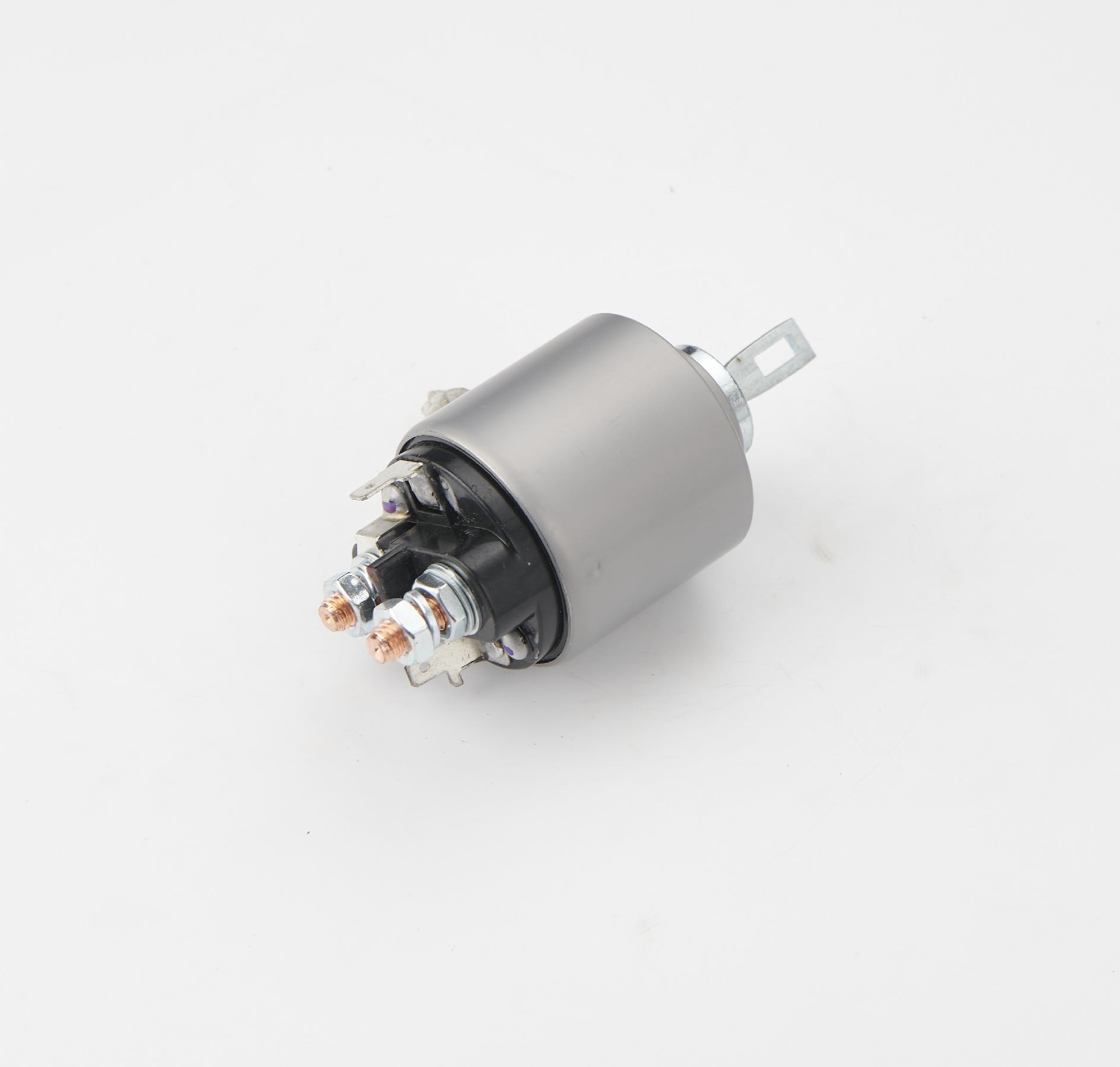
Modern automotive electrical systems rely heavily on reliable switching components, with the 12v starter solenoid serving as a critical bridge between your ignition system and starter motor. This electromagnetic switch handles the high current demands required to crank your engine while protecting sensitive ignition circuits from damage. Understanding proper wiring techniques and polarity requirements ensures optimal performance and prevents costly electrical failures that can leave you stranded.
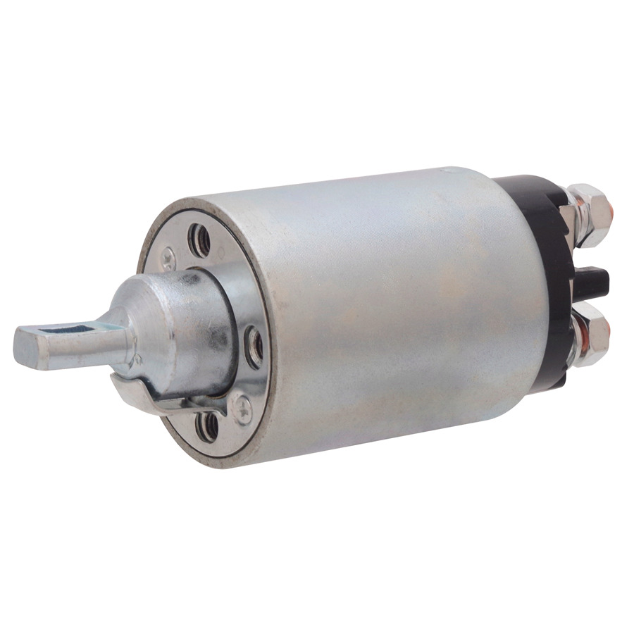
Professional mechanics and automotive enthusiasts recognize that improper 12v starter solenoid installation ranks among the leading causes of starter system failures. The consequences extend beyond mere inconvenience, often resulting in damaged starter motors, burned wiring harnesses, and compromised battery systems. This comprehensive guide addresses the fundamental principles of solenoid operation, proper wiring procedures, and critical safety measures that protect your investment.
Understanding 12V Starter Solenoid Operation Principles
Electromagnetic Switching Fundamentals
The 12v starter solenoid operates on electromagnetic principles, utilizing a coil-activated plunger mechanism to complete high-amperage circuits. When voltage is applied to the control terminal, the electromagnetic coil generates a magnetic field that pulls the internal plunger into engagement position. This action simultaneously closes two separate circuits: the primary starter motor circuit and a secondary bypass circuit that maintains engagement during cranking.
Internal construction typically features a heavy-duty copper contact disc mounted on the movable plunger assembly. This disc bridges the gap between two stationary terminals, creating a low-resistance path for starter motor current. The electromagnetic coil surrounds the plunger assembly and connects to the ignition switch through a smaller control wire. Understanding this dual-circuit operation proves essential for proper 12v starter solenoid diagnosis and installation.
Current Handling Capabilities and Specifications
Standard automotive 12v starter solenoid units handle continuous currents ranging from 150 to 400 amperes, depending on engine displacement and starter motor requirements. Peak engagement currents often exceed 500 amperes for brief periods during initial contact closure. These high current levels necessitate robust terminal construction and proper wire sizing to prevent overheating and voltage drops.
Coil resistance typically measures between 1.5 and 3.0 ohms, drawing approximately 4 to 8 amperes during activation. This relatively low control current allows the ignition switch to operate the 12v starter solenoid without excessive load on the switching contacts. Proper voltage supply ensures reliable engagement and prevents premature coil failure due to insufficient magnetic field strength.
Essential Wiring Components and Tools
Wire Selection and Sizing Requirements
Proper wire selection forms the foundation of reliable 12v starter solenoid installation. Battery-to-solenoid connections require 4 AWG or larger copper wire to handle peak starting currents without excessive voltage drop. Solenoid-to-starter connections typically use 2 AWG cable with heavy-duty terminals rated for automotive applications. Control circuit wiring can utilize 14 AWG or 16 AWG wire, provided the total circuit resistance remains within acceptable limits.
Quality terminal connectors prevent corrosion and ensure long-term reliability in harsh automotive environments. Marine-grade heat-shrink terminals offer superior moisture protection compared to standard crimp connectors. Apply dielectric grease to all connections to further reduce corrosion potential and maintain optimal conductivity throughout the service life of your 12v starter solenoid installation.
Professional Installation Tools and Equipment
Professional installation requires specific tools designed for automotive electrical work. A quality crimping tool ensures proper terminal compression and mechanical integrity. Digital multimeters enable accurate voltage and resistance measurements during testing and troubleshooting procedures. Wire strippers with multiple gauge settings prevent conductor damage during preparation.
Soldering equipment provides the most reliable connection method for permanent installations, though quality crimp connections remain acceptable for most applications. Heat guns facilitate proper heat-shrink terminal installation and wire harness protection. Torque specifications for 12v starter solenoid mounting bolts typically range from 15 to 25 foot-pounds, requiring an appropriate torque wrench for proper installation.
Step-by-Step Wiring Procedures
Battery Disconnect and Safety Preparation
Begin all electrical work by disconnecting the negative battery terminal to prevent accidental short circuits and potential injury. Remove the positive terminal connection as an additional safety measure when working with high-current circuits. Secure loose terminal ends to prevent accidental contact with grounded surfaces during the installation process.
Locate the existing 12v starter solenoid mounting position and inspect surrounding components for potential interference. Clean all mounting surfaces and terminal connections with appropriate solvents to ensure optimal conductivity. Document existing wire routing and terminal positions with digital photographs to facilitate proper reassembly.
Terminal Identification and Connection Sequence
Most 12v starter solenoid units feature four distinct terminals with specific functions. The large battery terminal receives the positive battery cable and supplies power to the system. The equally large starter terminal connects to the starter motor through heavy-gauge cable. The smaller ignition terminal receives 12-volt control signal from the ignition switch. The remaining terminal often connects to ignition bypass circuits or remains unused in modern applications.
Connect the battery positive cable to the designated battery terminal first, ensuring proper torque specification to prevent loose connections. Route the starter motor cable to minimize interference with moving components and potential heat sources. Install the ignition control wire with adequate service loop to accommodate engine movement during operation. Apply thread-locking compound to mounting bolts to prevent loosening due to engine vibration.
Reverse Polarity Prevention Strategies
Understanding Polarity-Related Damage
Reverse polarity connections represent one of the most destructive errors in 12v starter solenoid installation. Connecting battery cables with reversed polarity can instantly damage electronic control modules, alternator diodes, and sensitive ignition components. The electromagnetic coil within the solenoid may sustain permanent damage when subjected to reverse current flow.
Modern vehicles incorporate numerous electronic systems that cannot tolerate polarity reversal. Engine control modules, transmission controllers, and body control modules contain semiconductor components that fail immediately when exposed to reverse voltage. Replacement costs for these components often exceed several thousand dollars, making proper polarity verification absolutely critical.
Verification Methods and Testing Procedures
Use a digital multimeter to verify proper polarity before making final connections. Measure voltage between the battery positive terminal and vehicle ground to confirm positive polarity. Similarly, verify that the negative terminal shows negative potential relative to ground reference points.
Color-coded wiring harnesses provide visual confirmation of proper connections, with red indicating positive and black representing negative circuits. However, never rely solely on wire colors, as previous repairs may have introduced non-standard color coding. Physical verification using test equipment eliminates guesswork and prevents costly mistakes during 12v starter solenoid installation.
Common Installation Mistakes and Solutions
Wire Routing and Protection Issues
Improper wire routing ranks among the most frequent installation errors, leading to premature failure and safety hazards. Routing starter cables near exhaust components exposes the insulation to extreme temperatures that cause deterioration and potential short circuits. Similarly, cables routed through sharp metal edges risk mechanical damage during normal vehicle operation.
Inadequate protection against road debris and moisture infiltration compromises long-term reliability. Install protective conduit or split-loom tubing around exposed cable sections. Secure cables with appropriate clamps spaced at regular intervals to prevent movement-related fatigue. Ensure adequate clearance from moving components such as steering linkages and suspension members that could cause mechanical damage to your 12v starter solenoid wiring.
Terminal Connection and Torque Specifications
Loose terminal connections create high-resistance points that generate excessive heat and voltage drops. Under-torqued connections may appear secure initially but loosen over time due to thermal cycling and vibration. Conversely, over-torqued connections can damage terminal threads or deform contact surfaces, creating poor electrical connections.
Apply manufacturer-specified torque values using a calibrated torque wrench to ensure consistent clamping force. Clean all contact surfaces with fine sandpaper or wire brushes to remove oxidation and ensure optimal conductivity. Install lock washers or thread-locking compound where specified to maintain proper torque settings throughout the service life of the 12v starter solenoid installation.
Testing and Validation Procedures
Functional Testing Methods
Comprehensive testing validates proper 12v starter solenoid installation and identifies potential issues before they cause system failures. Begin with static resistance measurements across the coil terminals to verify proper electromagnetic function. Typical coil resistance should measure within manufacturer specifications, usually between 1.5 and 3.0 ohms.
Dynamic testing requires applying 12-volt control signal while monitoring contact closure and current flow. Use an ammeter to measure control circuit current draw, which should remain within specified limits. Excessive current draw indicates internal coil damage or short circuits that require immediate attention.
Performance Verification and Troubleshooting
Successful installation produces crisp solenoid engagement with minimal voltage drop across the main contacts. Measure voltage at the starter motor terminal during cranking to verify adequate power delivery. Voltage readings should remain within 0.5 volts of battery voltage under normal operating conditions.
Listen for proper engagement sounds during operation, as mechanical clicking indicates successful plunger movement. Sluggish engagement or multiple clicking sounds suggest insufficient control voltage or internal mechanical problems. Address these issues immediately to prevent damage to the starter motor or 12v starter solenoid components.
Maintenance and Long-Term Care
Preventive Maintenance Schedule
Regular maintenance extends the service life of your 12v starter solenoid installation and prevents unexpected failures. Inspect all connections annually for signs of corrosion, looseness, or heat damage. Clean terminals with appropriate solvents and apply fresh dielectric grease to maintain optimal conductivity.
Monitor starting system performance for changes in cranking speed or engagement characteristics. Document any irregularities and investigate promptly to prevent minor issues from developing into major failures. Replace corroded or damaged wiring harnesses before they compromise system reliability.
Environmental Protection Considerations
Harsh environmental conditions accelerate deterioration of electrical components and connections. Salt exposure from winter road treatments creates particularly aggressive corrosion conditions that attack metal components and wire insulation. Install additional protection such as spray-on coatings or protective covers where environmental exposure cannot be avoided.
Temperature extremes affect both mechanical and electrical performance of the 12v starter solenoid system. Cold weather increases battery internal resistance and reduces available cranking current. Hot weather accelerates component aging and increases resistance in electrical connections. Consider these factors when evaluating system performance and planning maintenance intervals.
FAQ
What happens if I connect the 12v starter solenoid with reverse polarity
Reverse polarity connections can cause immediate and catastrophic damage to your vehicle's electrical system. Electronic control modules, alternator diodes, and the solenoid's internal components may fail instantly when subjected to incorrect voltage polarity. Always verify connections with a multimeter before applying power to prevent expensive repairs.
How do I know if my 12v starter solenoid is failing
Common symptoms include clicking sounds without starter engagement, intermittent starting problems, or complete failure to engage. You may also notice burned or corroded terminals, excessive heat generation, or unusual electrical smells. Testing the coil resistance and contact continuity will confirm whether replacement is necessary.
Can I use any 12v starter solenoid as a replacement
While most automotive applications use standard 12-volt systems, solenoids differ in current capacity, terminal configuration, and mounting requirements. Always match the replacement unit to your specific vehicle's requirements, including amp rating and terminal positions. Using an undersized solenoid can result in premature failure and potential fire hazards.
What wire gauge should I use for 12v starter solenoid connections
Main power connections require 4 AWG or larger cable to handle the high starting currents, typically 150-400 amperes. Control circuit wiring can use 14 or 16 AWG wire since it only carries 4-8 amperes. Using undersized wire creates voltage drops and heat generation that can damage the entire starting system.
