EN
EN



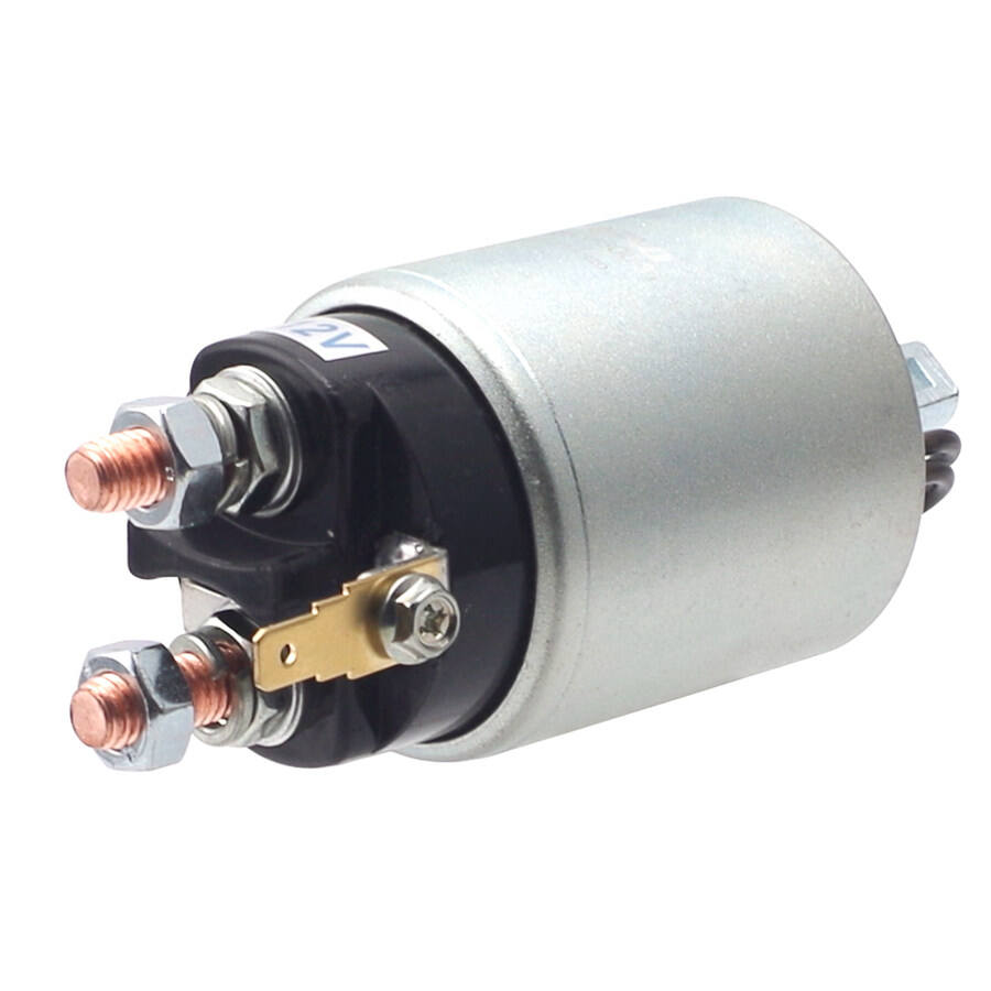
A solenoid switch serves as a critical component in various electrical and mechanical systems, controlling the flow of current through electromagnetic activation. When this essential device malfunctions, it can disrupt entire operational sequences, leading to costly downtime and reduced system efficiency. Understanding the common problems associated with solenoid switch operation and knowing how to implement quick fixes can save both time and resources while maintaining optimal system performance.
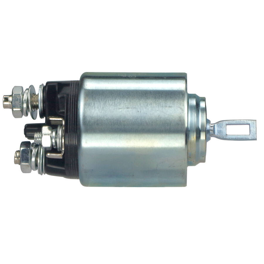
Industrial applications rely heavily on solenoid switch reliability, making proactive maintenance and troubleshooting skills invaluable for technicians and engineers. The electromagnetic nature of these switches means they are susceptible to specific failure modes that can often be identified and resolved through systematic diagnostic approaches. By recognizing early warning signs and implementing appropriate corrective measures, operators can extend equipment lifespan and maintain consistent operational reliability.
Understanding Solenoid Switch Fundamentals
Basic Operating Principles
The solenoid switch operates through electromagnetic induction, where an electrical current flowing through a coil creates a magnetic field that moves a plunger or armature. This mechanical movement either opens or closes electrical contacts, enabling the switch to control power flow to connected devices. The simplicity of this design contributes to the solenoid switch's widespread adoption across industries, from automotive applications to industrial automation systems.
Understanding the electromagnetic relationship between coil voltage, current draw, and mechanical force output is essential for proper troubleshooting. When voltage drops below specified thresholds or current exceeds rated limits, the solenoid switch may fail to operate correctly or experience accelerated wear. Temperature variations also affect coil resistance and magnetic field strength, potentially impacting switching performance under different environmental conditions.
Component Identification and Function
A typical solenoid switch consists of several key components including the electromagnetic coil, movable plunger or armature, spring return mechanism, and electrical contacts. Each component plays a specific role in the switching operation, and failure of any single element can compromise overall functionality. The coil generates the electromagnetic force, while the plunger translates this force into mechanical movement to actuate the contacts.
Contact materials and design significantly influence switching capacity and service life. Silver-based alloys provide excellent conductivity and arc resistance, while copper contacts offer good performance at lower costs. The spring return mechanism ensures proper contact positioning and provides the restoring force needed for reliable switching cycles. Understanding these components helps identify potential failure points and guides effective troubleshooting strategies.
Most Common Solenoid Switch Failures
Electrical Contact Problems
Contact-related failures represent the most frequent solenoid switch issues, often manifesting as intermittent operation, high resistance connections, or complete switching failure. Arcing during switching operations gradually erodes contact surfaces, creating pitted or burned areas that increase resistance and reduce current-carrying capacity. These damaged contacts may weld together under high current conditions or fail to make proper connection due to surface contamination.
Environmental factors accelerate contact degradation, with moisture, dust, and chemical vapors contributing to corrosion and oxidation. Regular inspection reveals early signs of contact wear, including discoloration, pitting, or material buildup. Measuring contact resistance with appropriate test equipment helps quantify degradation levels and determine whether cleaning, adjustment, or replacement is necessary to restore proper operation.
Coil and Electromagnetic Issues
Coil failures typically result from excessive heat, overvoltage conditions, or insulation breakdown over time. When a solenoid switch coil develops short circuits between windings or to ground, it may draw excessive current, overheat, or fail to generate sufficient magnetic force for proper operation. Open circuits in the coil completely prevent electromagnetic activation, rendering the switch inoperative.
Overheating represents a primary cause of coil failure, often resulting from continuous duty operation beyond rated specifications or inadequate heat dissipation. Ambient temperature extremes, poor ventilation, and proximity to heat sources compound thermal stress on coil insulation. Monitoring coil temperature and ensuring proper duty cycle operation helps prevent premature failures and extends solenoid switch service life significantly.
Diagnostic Techniques and Testing Methods
Visual Inspection Procedures
Systematic visual inspection provides valuable information about solenoid switch condition and potential failure modes. External examination reveals obvious damage such as burned or melted components, loose connections, or physical deformation. Checking for proper mounting alignment ensures that mechanical forces are properly distributed and that the plunger operates smoothly without binding or excessive friction.
Internal inspection requires careful disassembly and examination of contact surfaces, spring tension, and plunger movement. Look for signs of arcing damage, material transfer between contacts, or foreign debris that could interfere with proper operation. Document findings with photographs when possible to track degradation patterns over time and identify recurring issues that may indicate system-level problems.
Electrical Testing and Measurements
Comprehensive electrical testing begins with coil resistance measurements using a digital multimeter set to the appropriate ohm range. Compare measured values against manufacturer specifications to identify potential coil damage or deterioration. Insulation resistance testing between coil and ground using a megohmmeter helps detect insulation breakdown that could lead to ground faults or safety hazards.
Contact resistance measurements require specialized low-resistance ohmmeters or micro-ohmmeters capable of accurate readings in the milliohm range. High contact resistance indicates degraded surfaces that may cause excessive heating or voltage drops during operation. Dynamic testing under actual operating conditions provides the most accurate assessment of solenoid switch performance and helps identify intermittent problems that static tests might miss.
Quick Fix Solutions for Common Problems
Contact Cleaning and Maintenance
Contact cleaning represents one of the most effective quick fixes for solenoid switch problems, often restoring proper operation without component replacement. Use appropriate contact cleaning solutions and fine abrasive materials to remove oxidation, carbonization, or other surface contaminants. Avoid aggressive filing or sanding that could damage contact geometry or remove precious metal plating designed for optimal performance.
After cleaning, apply a thin layer of contact enhancer or protective coating to prevent future corrosion and improve conductivity. Ensure proper contact alignment and gap settings according to manufacturer specifications. Inadequate contact pressure or excessive gaps can cause arcing and accelerated wear, while excessive pressure may cause mechanical binding or premature spring fatigue in the solenoid switch assembly.
Voltage and Current Adjustments
Voltage-related issues often respond to supply voltage adjustments within acceptable ranges specified by the solenoid switch manufacturer. Low voltage conditions may prevent reliable switching, while overvoltage accelerates coil heating and insulation degradation. Use voltage regulators or transformers to maintain stable supply voltage under varying load conditions and ensure consistent switching performance.
Current limiting through series resistance or electronic controls helps protect solenoid switch coils from inrush current damage during initial energization. Implementing soft-start circuits or PWM control reduces mechanical shock and extends contact life by minimizing arcing during switching operations. These modifications often resolve intermittent operation issues without requiring major system redesign or component replacement.
Preventive Maintenance Strategies
Scheduled Inspection Protocols
Establishing regular inspection schedules based on operating hours, switching cycles, or calendar intervals helps identify potential solenoid switch problems before they cause system failures. Create detailed checklists covering visual examination, electrical measurements, and functional testing to ensure comprehensive evaluation. Document all findings in maintenance records to track performance trends and predict future service requirements.
Environmental monitoring plays a crucial role in preventive maintenance, as temperature, humidity, and contamination levels directly affect solenoid switch reliability. Install appropriate sensors and establish alarm thresholds to alert maintenance personnel when conditions exceed acceptable limits. Regular cleaning of switch enclosures and contact areas removes accumulated debris that could interfere with proper operation or accelerate component degradation.
Performance Monitoring and Data Analysis
Implementing continuous monitoring systems provides real-time data on solenoid switch performance parameters including coil current, switching times, and contact resistance. Trend analysis of this data reveals gradual degradation patterns that allow planned maintenance before failures occur. Modern monitoring systems can integrate with plant maintenance management systems to automatically schedule service based on actual component condition rather than arbitrary time intervals.
Statistical analysis of failure data helps identify root causes and optimize maintenance strategies for improved reliability. Track failure modes, operating conditions at time of failure, and service intervals to develop predictive models specific to each application. This data-driven approach to solenoid switch maintenance reduces both planned and unplanned downtime while optimizing resource allocation for maximum cost-effectiveness.
Advanced Troubleshooting Techniques
Oscilloscope Analysis and Waveform Interpretation
Advanced diagnostic techniques using oscilloscopes provide detailed insight into solenoid switch electrical behavior during operation. Monitoring coil current and voltage waveforms reveals switching characteristics, inrush current patterns, and potential timing issues that standard meters cannot detect. Abnormal waveforms often indicate specific problems such as contact bounce, arc duration, or electromagnetic interference affecting switch operation.
Current signature analysis compares operational waveforms against known good patterns to identify subtle degradation before obvious failures occur. This technique proves particularly valuable for critical applications where unexpected solenoid switch failures could result in safety hazards or significant economic losses. Training maintenance personnel in oscilloscope operation and waveform interpretation enhances diagnostic capabilities and reduces troubleshooting time significantly.
Thermal Imaging and Heat Analysis
Infrared thermography provides non-contact measurement of solenoid switch temperatures during operation, revealing hot spots that indicate potential problems. Overheating contacts, coils, or connections appear as elevated temperature zones in thermal images, allowing targeted maintenance before failures occur. Regular thermal surveys help establish baseline temperature patterns and identify deviations that warrant further investigation.
Thermal analysis extends beyond simple temperature measurement to include heat dissipation patterns, thermal cycling effects, and ambient temperature influences on solenoid switch performance. Understanding thermal behavior helps optimize installation locations, improve ventilation, and select appropriate switch ratings for specific applications. This comprehensive approach to thermal management significantly extends component life and improves system reliability.
Replacement and Upgrade Considerations
Compatibility Assessment and Selection Criteria
When quick fixes prove insufficient, solenoid switch replacement becomes necessary to restore proper system operation. Compatibility assessment involves matching electrical specifications including coil voltage, current ratings, contact capacity, and switching frequency requirements. Mechanical considerations such as mounting dimensions, plunger stroke, and operating force must also align with existing system constraints to ensure proper installation and operation.
Modern solenoid switch designs often incorporate improved materials, enhanced coil insulation, and better contact alloys that provide superior performance compared to older units. Evaluating upgrade opportunities during replacement decisions can improve reliability, reduce maintenance requirements, and extend service intervals. Consider environmental ratings, certification requirements, and long-term availability when selecting replacement components for critical applications.
Installation Best Practices and Integration
Proper installation techniques significantly impact solenoid switch reliability and service life. Ensure adequate clearances for heat dissipation, protect against environmental contamination, and provide secure mounting to prevent vibration-induced failures. Follow manufacturer torque specifications for electrical connections and use appropriate wire gauges to minimize voltage drops that could affect switching performance.
System integration considerations include electromagnetic compatibility, control circuit design, and protective device coordination. Install appropriate surge suppression, fusing, and filtering to protect the solenoid switch from electrical transients and interference. Verify that control signals meet timing and voltage requirements for reliable operation under all anticipated operating conditions.
FAQ
What causes a solenoid switch to stick in the closed position
Solenoid switch sticking typically results from welded contacts due to excessive current, foreign debris preventing plunger movement, or weakened return spring tension. High inrush currents or overload conditions can cause contact welding, while contamination from dust, moisture, or chemical vapors may interfere with mechanical operation. Regular cleaning and proper current limiting help prevent these issues.
How do you test if a solenoid switch is working properly
Testing involves measuring coil resistance with a multimeter, checking for proper voltage supply, and verifying contact continuity during switching operations. Apply rated voltage to the coil while monitoring contact operation with a continuity tester or ohmmeter. Listen for the characteristic clicking sound that indicates mechanical movement, and measure switching times to ensure they fall within acceptable ranges.
Why does my solenoid switch draw excessive current
Excessive current draw usually indicates coil problems such as shorted windings, insulation breakdown, or mechanical binding that prevents complete plunger travel. Overvoltage conditions, contaminated contacts, or incorrect duty cycle operation can also increase current consumption beyond normal levels. Measure coil resistance and compare against specifications to identify electrical faults requiring repair or replacement.
How often should solenoid switches be inspected and maintained
Inspection frequency depends on application severity, environmental conditions, and switching frequency, but quarterly visual inspections and annual electrical testing provide good baseline maintenance for most applications. High-duty cycle or critical applications may require monthly inspections, while clean, low-frequency applications might extend intervals to semi-annually. Monitor performance trends to optimize maintenance scheduling based on actual operating conditions and failure history.