Ford trucks manufactured before 1995 require specific wiring configurations for their starter systems, particularly when dealing with ford starter solenoid installations. Understanding the electrical pathways and proper connection procedures ensures reliable engine starting performance across various Ford truck models from this era. Many truck owners encounter challenges when retrofitting or replacing their original starter components, making proper wiring knowledge essential for successful repairs and upgrades.
Pre-1995 Ford trucks utilized different electrical architectures compared to modern vehicles, requiring specialized attention to wire gauge, terminal placement, and ground connections. The ford starter solenoid serves as the critical link between the ignition switch and starter motor, controlling the high-amperage current flow necessary for engine cranking. Proper installation involves understanding both the control circuit and power circuit components within the starting system.
Understanding Pre-1995 Ford Starter System Architecture
Control Circuit Fundamentals
The control circuit in pre-1995 Ford trucks operates on a lower voltage system that activates the ford starter solenoid through the ignition switch. This circuit typically uses 12-volt power from the battery, routed through the ignition switch, neutral safety switch, and clutch pedal switch where applicable. The control circuit draws minimal current, usually less than 10 amperes, making it safe for standard automotive wiring practices.
Wire colors for the control circuit follow Ford's standard coding system, with the ignition feed typically using a red wire with white stripe or solid red configuration. The neutral safety switch connection often employs a purple wire, while ground connections use black wiring throughout the system. Understanding these color codes prevents misconnections that could damage electrical components or create safety hazards during installation.
Power Circuit Configuration
The power circuit handles the substantial current required by the starter motor, often exceeding 200 amperes during engine cranking. This circuit connects directly from the battery positive terminal to the ford starter solenoid main terminal, then continues to the starter motor through heavy-gauge cable. The solenoid acts as a remote-controlled switch, engaging when the control circuit activates and allowing full battery power to reach the starter.
Cable sizing for the power circuit requires careful consideration of voltage drop and current capacity. Most pre-1995 Ford trucks use 4-gauge or 2-gauge welding cable for the main power connection, depending on engine size and electrical demands. Proper terminal crimping and secure connections prevent voltage losses that could result in slow cranking or starting failures, particularly in cold weather conditions.
Wiring Installation Procedures
Terminal Identification and Connection
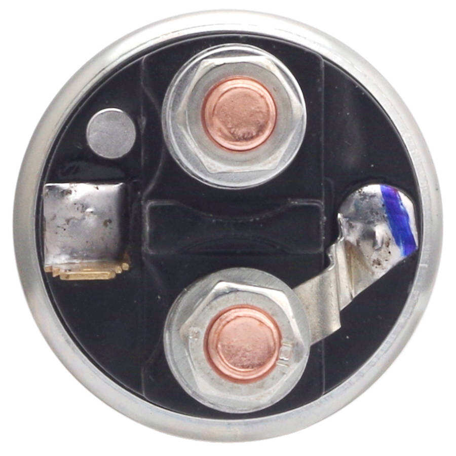
Modern ford starter solenoid units feature clearly marked terminals that correspond to specific circuit functions. The large terminals handle the power circuit connections, with one connecting to the battery positive cable and the other feeding the starter motor. Smaller terminals accommodate the control circuit wiring, including the ignition switch feed and any auxiliary connections required by the specific Ford truck model.
Terminal torque specifications vary by manufacturer but typically range from 10 to 15 foot-pounds for control circuit connections and 25 to 35 foot-pounds for power circuit terminals. Using proper torque prevents loose connections that could create resistance, heat buildup, or intermittent starting problems. Anti-corrosion compound applied to terminal surfaces extends service life and maintains reliable electrical contact over time.
Routing and Protection Methods
Proper wire routing protects the ford starter solenoid circuits from heat, mechanical damage, and electrical interference. Control circuit wiring should follow existing harness paths when possible, using factory mounting points and protective conduit where available. Power circuit cables require separation from exhaust components and moving parts that could cause abrasion or heat damage over time.
Protection devices include inline fuses for control circuits and fusible links for power circuits, preventing damage from electrical faults or short circuits. The control circuit typically uses a 10-ampere fuse installed in the truck's fuse panel, while the power circuit relies on a fusible link rated 30 to 50 amperes higher than normal operating current. These protective measures safeguard both the solenoid and surrounding electrical components from overcurrent conditions.
Retrofit Compatibility Considerations
Voltage System Matching
Pre-1995 Ford trucks operate on 12-volt electrical systems, requiring ford starter solenoid units designed for this voltage range. While most modern solenoids maintain compatibility with older systems, verification of voltage ratings prevents damage from mismatched components. Operating voltage tolerance typically ranges from 10.8 to 14.4 volts, accommodating normal battery and charging system variations.
Temperature compensation features in quality solenoids ensure consistent operation across the wide temperature ranges encountered in automotive applications. Cold weather operation requires solenoids capable of reliable engagement at temperatures as low as minus 40 degrees Fahrenheit, while summer conditions may exceed 200 degrees Fahrenheit under hood. Modern solenoid designs incorporate materials and coil windings that maintain performance across these extreme conditions.
Physical Mounting Requirements
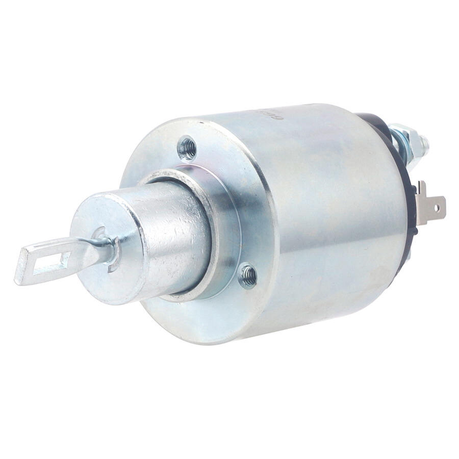
Mounting location affects both performance and longevity of the ford starter solenoid installation. Pre-1995 Ford trucks typically mount the solenoid on the firewall or inner fender well, providing protection from road debris while maintaining accessibility for service. The mounting surface must provide adequate support for the solenoid weight and withstand vibration forces generated during engine operation.
Clearance requirements include sufficient space for cable connections and heat dissipation around the solenoid body. Minimum clearance of two inches from exhaust components prevents heat-related failures, while adequate access space facilitates future maintenance and troubleshooting procedures. Rubber mounting isolators reduce vibration transmission and extend solenoid service life in demanding applications.
Testing and Troubleshooting Methods
Electrical Continuity Verification
Proper testing procedures verify correct ford starter solenoid installation and identify potential problems before they cause starting failures. Continuity testing using a digital multimeter confirms proper connections between terminals and ensures the control circuit operates within specified parameters. Resistance measurements across solenoid coil windings should fall within manufacturer specifications, typically ranging from 1.5 to 4.0 ohms for most applications.
Voltage drop testing under load conditions reveals connection problems that may not appear during static testing. With the engine cranking, voltage measurements at various points throughout the starting circuit identify high-resistance connections or undersized wiring. Acceptable voltage drop limits include 0.5 volts maximum across all connections in the power circuit and 0.1 volts maximum in control circuit connections.
Performance Validation Procedures
Functional testing confirms the ford starter solenoid operates correctly under actual starting conditions. Cranking speed measurements using an inductive pickup and digital tachometer verify adequate power delivery to the starter motor. Minimum cranking speeds vary by engine size but typically require 150 to 200 RPM for reliable starting in most Ford truck applications.
Current draw testing identifies problems within the starting system that could affect solenoid performance or longevity. Normal starter current ranges from 150 to 300 amperes depending on engine size, temperature, and oil viscosity. Excessive current draw may indicate internal starter problems, while insufficient current suggests high resistance in the power circuit or weak battery conditions.
Maintenance and Service Recommendations
Preventive Care Practices
Regular maintenance extends ford starter solenoid service life and prevents unexpected starting failures. Visual inspection every six months identifies corrosion, loose connections, or physical damage that could affect performance. Terminal cleaning using appropriate contact cleaner removes oxidation and ensures reliable electrical connections, while protective coatings prevent future corrosion formation.
Connection torque verification should be performed annually or whenever electrical work is conducted on the starting system. Thermal cycling from normal operation can cause terminals to loosen over time, creating high-resistance connections that generate heat and reduce system reliability. Proper torque application using calibrated tools ensures optimal electrical contact without overtightening that could damage terminals or threads.
Replacement Indicators and Scheduling
Service life expectations for quality ford starter solenoid units range from 100,000 to 200,000 miles under normal operating conditions. Factors affecting longevity include operating environment, electrical system maintenance, and starting frequency. Harsh conditions such as extreme temperatures, high humidity, or frequent short trips may reduce service intervals and require more frequent inspection.
Warning signs indicating potential solenoid problems include intermittent starting, clicking sounds during cranking attempts, or complete failure to engage the starter motor. Early detection and replacement prevent secondary damage to starter motors or electrical system components. Proactive replacement based on age or mileage intervals ensures reliable vehicle operation and reduces the risk of roadside failures.
FAQ
What wire gauge is required for ford starter solenoid power connections in pre-1995 trucks
Pre-1995 Ford trucks typically require 4-gauge welding cable for the main power connection between the battery and ford starter solenoid, with 2-gauge cable recommended for larger engines or high-performance applications. The control circuit uses 14-gauge or 12-gauge wire depending on the length of the run and current requirements. Proper wire sizing prevents voltage drop that could cause slow cranking or starting failures.
Can modern starter solenoids be used to replace original equipment in older Ford trucks
Modern ford starter solenoid units are generally compatible with pre-1995 Ford trucks, provided they match the voltage rating and terminal configuration of the original equipment. Most quality aftermarket solenoids offer improved reliability and longevity compared to original components while maintaining full compatibility with existing wiring harnesses. Verification of mounting dimensions and electrical specifications ensures proper fit and function.
How do I identify the correct terminals on a ford starter solenoid for wiring connections
Ford starter solenoid terminals are typically marked with letters or numbers indicating their function. The large terminals handle battery power input and starter motor output, while smaller terminals accommodate the ignition switch feed and auxiliary connections. Most solenoids include wiring diagrams or terminal identification guides that specify proper connections for different Ford truck models and years.
What causes intermittent starting problems with ford starter solenoid installations
Intermittent starting problems with ford starter solenoid systems often result from loose connections, corroded terminals, or internal solenoid wear. Heat cycling can cause terminals to expand and contract, creating intermittent contact that affects reliability. Regular maintenance including terminal cleaning, torque verification, and visual inspection helps prevent these issues and ensures consistent starting performance.
Table of Contents
- Understanding Pre-1995 Ford Starter System Architecture
- Wiring Installation Procedures
- Retrofit Compatibility Considerations
- Testing and Troubleshooting Methods
- Maintenance and Service Recommendations
-
FAQ
- What wire gauge is required for ford starter solenoid power connections in pre-1995 trucks
- Can modern starter solenoids be used to replace original equipment in older Ford trucks
- How do I identify the correct terminals on a ford starter solenoid for wiring connections
- What causes intermittent starting problems with ford starter solenoid installations